GENOSYL- nitric oxide gas
GENOSYL by
Drug Labeling and Warnings
GENOSYL by is a Prescription medication manufactured, distributed, or labeled by VERO BIOTECH, INC.. Drug facts, warnings, and ingredients follow.
Drug Details [pdf]
-
HIGHLIGHTS OF PRESCRIBING INFORMATION
These highlights do not include all the information needed to use GENOSYL ®safely and effectively. See full prescribing information for GENOSYL.
GENOSYL (nitric oxide), for inhalation use
Initial U.S. Approval: 1999INDICATIONS AND USAGE
GENOSYL is a vasodilator indicated to improve oxygenation and reduce the need for extracorporeal membrane oxygenation in term and near-term (>34 weeks gestation) neonates with hypoxic respiratory failure associated with clinical or echocardiographic evidence of pulmonary hypertension in conjunction with ventilatory support and other appropriate agents ( 1).
DOSAGE AND ADMINISTRATION
The recommended dose is 20 ppm, maintained for up to 14 days or until the underlying oxygen desaturation has resolved ( 2.1).
DOSAGE FORMS AND STRENGTHS
GENOSYL (nitric oxide) is a gas, available at concentrations up to 800 ppm. (3)
CONTRAINDICATIONS
Neonates dependent on right-to-left shunting of blood ( 4).
WARNINGS AND PRECAUTIONS
Rebound Pulmonary Hypertension: Abrupt discontinuation of GENOSYL may lead to worsening oxygenation and increasing pulmonary artery pressure ( 5.1).
Methemoglobinemia: Methemoglobin increases with the dose of nitric oxide; following discontinuation or reduction of nitric oxide, methemoglobin levels return to baseline over a period of hours ( 5.2).
Elevated NO 2Levels: Monitor NO 2levels ( 5.3).
Heart Failure: In patients with pre-existing left ventricular dysfunction, GENOSYL may increase pulmonary capillary wedge pressure leading to pulmonary edema ( 5.4).
ADVERSE REACTIONS
The most common adverse reaction is hypotension ( 6).
To report SUSPECTED ADVERSE REACTIONS, contact Vero Biotech at 1-877-337-4118 and http://www.vero-biotech.com/ or FDA at 1-800-FDA-1088 or www.fda.gov/medwatch.
DRUG INTERACTIONS
Nitric oxide donor compounds may increase the risk of developing methemoglobinemia ( 7).
Revised: 8/2024
-
Table of Contents
FULL PRESCRIBING INFORMATION: CONTENTS*
1 INDICATIONS AND USAGE
2 DOSAGE AND ADMINISTRATION
2.1 Dosage
2.2 Administration
3 DOSAGE FORMS AND STRENGTHS
4 CONTRAINDICATIONS
5 WARNINGS AND PRECAUTIONS
5.1 Rebound Pulmonary Hypertension Syndrome following Abrupt Discontinuation
5.2 Hypoxemia from Methemoglobinemia
5.3 Airway Injury from Nitrogen Dioxide
5.4 Worsening Heart Failure
6 ADVERSE REACTIONS
6.1 Clinical Trials Experience
6.2 Postmarketing Experience
7 DRUG INTERACTIONS
7.1 Nitric Oxide Donor Agents
8 USE IN SPECIFIC POPULATIONS
8.4 Pediatric Use
8.5 Geriatric Use
10 OVERDOSAGE
11 DESCRIPTION
12 CLINICAL PHARMACOLOGY
12.1 Mechanism of Action
12.2 Pharmacodynamics
12.3 Pharmacokinetics
13 NONCLINICAL TOXICOLOGY
13.1 Carcinogenesis, Mutagenesis, Impairment of Fertility
14 CLINICAL STUDIES
14.1 Treatment of Hypoxic Respiratory Failure (HRF)
14.2 Ineffective in Adult Respiratory Distress Syndrome (ARDS)
14.3 Ineffective in Prevention of Bronchopulmonary Dysplasia (BPD)
16 HOW SUPPLIED/STORAGE AND HANDLING
- * Sections or subsections omitted from the full prescribing information are not listed.
-
1 INDICATIONS AND USAGE
GENOSYL ®is indicated to improve oxygenation and reduce the need for extracorporeal membrane oxygenation in term and near-term (>34 weeks gestation) neonates with hypoxic respiratory failure associated with clinical or echocardiographic evidence of pulmonary hypertension in conjunction with ventilatory support and other appropriate agents.
-
2 DOSAGE AND ADMINISTRATION
2.1 Dosage
Term and near-term neonates with hypoxic respiratory failure
The recommended dose of GENOSYL is 20 ppm. Maintain treatment up to 14 days or until the underlying oxygen desaturation has resolved and the neonate is ready to be weaned from GENOSYL therapy.
Doses greater than 20 ppm are not recommended [see Warnings and Precautions (5.2)].
2.2 Administration
Nitric Oxide Delivery System
GENOSYL must be administered using a calibrated GENOSYL Delivery System. Only validated ventilator systems should be used in conjunction with GENOSYL [see Description (11)].
Consult the GENOSYL Delivery System Operator's Manual or call 1-877-337-4118 or visit www.vero-biotech.com for needed information on training and technical support for users of GENOSYL with the GENOSYL Delivery System .
Keep available a backup power supply to address power failures. The GENOSYL Delivery System consists of a primary system and a fully functional second system that can be used as backup in the event of primary system failure.
Monitoring
Measure methemoglobin within 4-8 hours after initiation of treatment with GENOSYL and periodically throughout treatment [see Warnings and Precautions (5.2)].
Monitor for PaO 2and inspired NO 2during GENOSYL administration [see Warnings and Precautions 5.3)].
Weaning and Discontinuation
Avoid abrupt discontinuation of GENOSYL [see Warnings and Precautions (5.1)]. To wean GENOSYL, down titrate in several steps, pausing several hours at each step to monitor for hypoxemia.
- 3 DOSAGE FORMS AND STRENGTHS
- 4 CONTRAINDICATIONS
-
5 WARNINGS AND PRECAUTIONS
5.1 Rebound Pulmonary Hypertension Syndrome following Abrupt Discontinuation
Wean from GENOSYL [see Dosage and Administration (2.2)]. Abrupt discontinuation of GENOSYL may lead to worsening oxygenation and increasing pulmonary artery pressure, i.e., Rebound Pulmonary Hypertension Syndrome. Signs and symptoms of Rebound Pulmonary Hypertension Syndrome include hypoxemia, systemic hypotension, bradycardia, and decreased cardiac output. If Rebound Pulmonary Hypertension occurs, reinstate GENOSYL therapy immediately.
5.2 Hypoxemia from Methemoglobinemia
Nitric oxide combines with hemoglobin to form methemoglobin, which does not transport oxygen. Methemoglobin levels increase with the dose of GENOSYL; it can take 8 hours or more before steady-state methemoglobin levels are attained. Monitor methemoglobin and adjust the dose of GENOSYL to optimize oxygenation.
If methemoglobin levels do not resolve with decrease in dose or discontinuation of GENOSYL, additional therapy may be warranted to treat methemoglobinemia [see Overdosage (10)] .
5.3 Airway Injury from Nitrogen Dioxide
Nitrogen dioxide (NO 2) forms in gas mixtures containing NO and O 2. Nitrogen dioxide may cause airway inflammation and damage to lung tissues.
If there is an unexpected change in NO 2concentration, or if the NO 2concentration reaches 0.5 ppm when measured in the breathing circuit, then the delivery system should be assessed in accordance with the GENOSYL Delivery System Operator's Manual troubleshooting section, and the NO 2analyzer should be recalibrated. The dose of GENOSYL and/or FiO 2should be adjusted as appropriate.
5.4 Worsening Heart Failure
Patients with left ventricular dysfunction treated with GENOSYL may experience pulmonary edema, increased pulmonary capillary wedge pressure, worsening of left ventricular dysfunction, systemic hypotension, bradycardia and cardiac arrest. Discontinue GENOSYL while providing symptomatic care.
-
6 ADVERSE REACTIONS
The following adverse reactions are discussed elsewhere in the label;
Hypoxemia [see Warnings and Precautions (5.2)]
Worsening Heart Failure [see Warnings and Precautions (5.4)]
6.1 Clinical Trials Experience
Because clinical trials are conducted under widely varying conditions, adverse reaction rates observed in the clinical trials of a drug cannot be directly compared to rates in the clinical trials of another drug and may not reflect the rates observed in practice. The adverse reaction information from the clinical studies does, however, provide a basis for identifying the adverse events that appear to be related to drug use and for approximating rates.
Controlled studies have included 325 patients on nitric oxide doses of 5 to 80 ppm and 251 patients on placebo. Total mortality in the pooled trials was 11% on placebo and 9% on nitric oxide gas for inhalation, a result adequate to exclude nitric oxide mortality being more than 40% worse than placebo.
In both the NINOS and CINRGI studies, the duration of hospitalization was similar in nitric oxide gas for inhalation and placebo-treated groups.
From all controlled studies, at least 6 months of follow-up is available for 278 patients who received nitric oxide gas and 212 patients who received placebo. Among these patients, there was no evidence of an adverse effect of treatment on the need for re-hospitalization, special medical services, pulmonary disease, and neurological sequelae.
In the NINOS study, treatment groups were similar with respect to the incidence and severity of intracranial hemorrhage, Grade IV hemorrhage, periventricular leukomalacia, cerebral infarction, seizures requiring anticonvulsant therapy, pulmonary hemorrhage, or gastrointestinal hemorrhage.
In CINRGI, the only adverse reaction (>2% higher incidence on nitric oxide gas for inhalation than on placebo) was hypotension (14% vs. 11%).
- 7 DRUG INTERACTIONS
-
8 USE IN SPECIFIC POPULATIONS
8.4 Pediatric Use
The safety and efficacy of nitric oxide for inhalation has been demonstrated in term and near-term neonates with hypoxic respiratory failure associated with evidence of pulmonary hypertension [see Clinical Studies (14.1)] . Additional studies conducted in premature neonates for the prevention of bronchopulmonary dysplasia have not demonstrated substantial evidence of efficacy [see Clinical Studies (14.3)]. No information about its effectiveness in other age populations is available.
-
10 OVERDOSAGE
Overdosage with nitric oxide gas is manifest by elevations in methemoglobin and pulmonary toxicities associated with inspired NO 2. Elevated NO 2may cause acute lung injury. Elevations in methemoglobin reduce the oxygen delivery capacity of the circulation. In clinical studies, NO 2levels >3 ppm or methemoglobin levels >7% were treated by reducing the dose of, or discontinuing, nitric oxide gas.
Methemoglobinemia that does not resolve after reduction or discontinuation of therapy can be treated with intravenous vitamin C, intravenous methylene blue, or blood transfusion, based upon the clinical situation.
-
11 DESCRIPTION
GENOSYL (nitric oxide) is administered by inhalation. Nitric oxide is a pulmonary vasodilator. Nitric oxide is generated from liquid dinitrogen tetroxide (N 2O 4) by the Cassette in the GENOSYL Delivery System. Upon initiation of GENOSYL Delivery System, the liquid N 2O 4is heated and the equilibrium shifts to nitrogen dioxide (NO 2) gas. The NO 2is then converted into nitric oxide (NO) using the antioxidant Cartridges, and nitric oxide is delivered to the patient by means of a ventilator or a nasal cannula. The amount of nitric oxide administered to the patient is set by controlling the temperature of the N 2O 4liquid module, which controls the pressure inside the liquid module, which in turn controls the mass of NO 2that is sent to the primary Cartridges, and hence the mass of nitric oxide. The mass flow of nitric oxide, together with the air from the pump, control the nitric oxide concentration. A nitric oxide sensor monitors the nitric oxide in the patient line. GENOSYL Delivery System is designed to deliver a controlled level of nitric oxide blended with breathing air or oxygen-enriched breathing air.
The GENOSYL Delivery System controls the flow of nitric oxide mixed with air delivered to the patient.
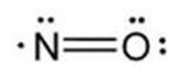
The structural formula of nitric oxide (NO) is shown below:
-
12 CLINICAL PHARMACOLOGY
12.1 Mechanism of Action
Nitric oxide relaxes vascular smooth muscle by binding to the heme moiety of cytosolic guanylate cyclase, activating guanylate cyclase and increasing intracellular levels of cyclic guanosine 3',5'-monophosphate, which then leads to vasodilation. When inhaled, nitric oxide selectively dilates the pulmonary vasculature, and because of efficient scavenging by hemoglobin, has minimal effect on the systemic vasculature.
GENOSYL appears to increase the partial pressure of arterial oxygen (PaO 2) by dilating pulmonary vessels in better ventilated areas of the lung, redistributing pulmonary blood flow away from lung regions with low ventilation/perfusion (V/Q) ratios toward regions with normal ratios.
12.2 Pharmacodynamics
Effects on Pulmonary Vascular Tone in PPHN
Persistent pulmonary hypertension of the newborn (PPHN) occurs as a primary developmental defect or as a condition secondary to other diseases such as meconium aspiration syndrome (MAS), pneumonia, sepsis, hyaline membrane disease, congenital diaphragmatic hernia (CDH), and pulmonary hypoplasia. In these states, pulmonary vascular resistance (PVR) is high, which results in hypoxemia secondary to right-to-left shunting of blood through the patent ductus arteriosus and foramen ovale. In neonates with PPHN, nitric oxide gas for inhalation improves oxygenation (as indicated by significant increases in PaO 2).
12.3 Pharmacokinetics
The pharmacokinetics of nitric oxide has been studied in adults.
Absorption and Distribution
Nitric oxide is absorbed systemically after inhalation. Most of it traverses the pulmonary capillary bed where it combines with hemoglobin that is 60% to 100% oxygen-saturated. At this level of oxygen saturation, nitric oxide combines predominantly with oxyhemoglobin to produce methemoglobin and nitrate. At low oxygen saturation, nitric oxide can combine with deoxyhemoglobin to transiently form nitrosylhemoglobin, which is converted to nitrogen oxides and methemoglobin upon exposure to oxygen. Within the pulmonary system, nitric oxide can combine with oxygen and water to produce nitrogen dioxide and nitrite, respectively, which interact with oxyhemoglobin to produce methemoglobin and nitrate. Thus, the end products of nitric oxide that enter the systemic circulation are predominantly methemoglobin and nitrate.
Metabolism
Methemoglobin disposition has been investigated as a function of time and nitric oxide exposure concentration in neonates with respiratory failure. The methemoglobin (MetHb) concentration-time profiles during the first 12 hours of exposure to 0, 5, 20, and 80 ppm nitric oxide are shown in Figure 1.
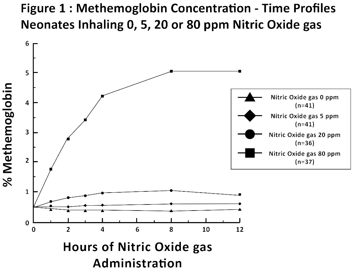
Methemoglobin concentrations increased during the first 8 hours of nitric oxide exposure. The mean methemoglobin level remained below 1% in the placebo group and in the 5 ppm and 20 ppm nitric oxide gas groups, but reached approximately 5% in the 80 ppm nitric oxide gas group. Methemoglobin levels >7% were attained only in patients receiving 80 ppm, where they comprised 35% of the group. The average time to reach peak methemoglobin was 10 ± 9 (SD) hours (median, 8 hours) in these 13 patients, but one patient did not exceed 7% until 40 hours.
-
13 NONCLINICAL TOXICOLOGY
13.1 Carcinogenesis, Mutagenesis, Impairment of Fertility
No evidence of a carcinogenic effect was apparent, at inhalation exposures up to the recommended dose (20 ppm), in rats for 20 hr/day for up to two years. Higher exposures have not been investigated.
Nitric oxide gas has demonstrated genotoxicity in Salmonella (Ames Test), human lymphocytes, and after in vivo exposure in rats. There are no animal or human studies to evaluate nitric oxide for effects on fertility.
-
14 CLINICAL STUDIES
14.1 Treatment of Hypoxic Respiratory Failure (HRF)
The efficacy of nitric oxide gas was investigated in term and near-term newborns with hypoxic respiratory failure (HRF) resulting from a variety of etiologies. Inhalation of nitric oxide gas reduces the oxygenation index (OI= mean airway pressure in cm H 2O × fraction of inspired oxygen concentration [FiO 2]× 100 divided by systemic arterial concentration in mmHg [PaO 2]) and increases PaO 2[see Clinical Pharmacology (12.1)].
NINOS Study
The Neonatal Inhaled Nitric Oxide Study (NINOS) was a double-blind, randomized, placebo-controlled, multicenter trial in 235 neonates with hypoxic respiratory failure. The objective of the study was to determine whether inhaled nitric oxide would reduce the occurrence of death and/or initiation of extracorporeal membrane oxygenation (ECMO) in a prospectively defined cohort of term or near-term neonates with hypoxic respiratory failure unresponsive to conventional therapy. Hypoxic respiratory failure was caused by meconium aspiration syndrome (MAS; 49%), pneumonia/sepsis (21%), idiopathic primary pulmonary hypertension of the newborn (PPHN; 17%), or respiratory distress syndrome (RDS; 11%). Infants ≤14 days of age (mean, 1.7 days) with a mean PaO 2of 46 mmHg and a mean oxygenation index (OI) of 43 cm H 2O / mmHg were initially randomized to receive 100% O 2with (n=114) or without (n=121) 20 ppm nitric oxide for up to 14 days. Response to study drug was defined as a change from baseline in PaO 230 minutes after starting treatment (full response = >20 mmHg, partial = 10–20 mmHg, no response = <10 mmHg). Neonates with a less than full response were evaluated for a response to 80 ppm nitric oxide or control gas. The primary results of this study are presented in Table 1.
Table 1: Summary of Clinical Results from Hypoxic Respiratory Failure Study Control
(n=121)Nitric Oxide gas (n=114) P value - * Extracorporeal membrane oxygenation
- † Death or need for ECMO was the primary end point of this study
Death or ECMO *,† 77 (64%) 52 (46%) 0.006 Death 20 (17%) 16 (14%) 0.60 ECMO 66 (55%) 44 (39%) 0.014 Although the incidence of death by 120 days of age was similar in both groups (NO, 14%; control 17%), significantly fewer infants in the nitric oxide group required ECMO compared with controls (39% vs. 55%, p = 0.014). The combined incidence of death and/or initiation of ECMO showed a significant advantage for the nitric oxide treated group (46% vs. 64%, p = 0.006). The nitric oxide group also had significantly greater increases in PaO 2and greater decreases in the OI and the alveolar-arterial oxygen gradient than the control group (p<0.001 for all parameters). Significantly more patients had at least a partial response to the initial administration of study drug in the nitric oxide group (66%) than the control group (26%, p<0.001). Of the 125 infants who did not respond to 20 ppm nitric oxide control, similar percentages of NO-treated (18%) and control (20%) patients had at least a partial response to 80 ppm nitric oxide gas for inhalation or control drug, suggesting a lack of additional benefit for the higher dose of nitric oxide. No infant had study drug discontinued for toxicity. Inhaled nitric oxide gas had no detectable effect on mortality. The adverse events collected in the NINOS trial occurred at similar incidence rates in both treatment groups [see Adverse Reactions (6.1)] . Follow-up exams were performed at 18-24 months for the infants enrolled in this trial. In the infants with available follow-up, the two treatment groups were similar with respect to their mental, motor, audiologic, or neurologic evaluations.
CINRGI Study
This study was a double-blind, randomized, placebo-controlled, multi-center trial of 186 term and near-term neonates with pulmonary hypertension and hypoxic respiratory failure. The primary objective of the study was to determine whether nitric oxide gas would reduce the receipt of ECMO in these patients. Hypoxic respiratory failure was caused by MAS (35%), idiopathic PPHN (30%), pneumonia/sepsis (24%), or RDS (8%). Patients with a mean PaO 2of 54 mmHg and a mean OI of 44 cm H 2O / mmHg were randomly assigned to receive either 20 ppm nitric oxide gas (n=97) or nitrogen gas (placebo; n=89) in addition to their ventilatory support. Patients who exhibited a PaO 2>60 mmHg and a pH < 7.55 were weaned to 5 ppm nitric oxide gas or placebo. The primary results from the CINRGI study are presented in Table 2.
Table 2: Summary of Clinical Results from Persistent Pulmonary Hypertension of the Newborn Study Placebo Nitric oxide gas P value - * Extracorporeal membrane oxygenation
- † ECMO was the primary end point of this study
ECMO *,† 51/89 (57%) 30/97 (31%) <0.001 Death 5/89 (6%) 3/97 (3%) 0.48 Significantly fewer neonates in the nitric oxide gas group required ECMO compared to the control group (31% vs. 57%, p<0.001). While the number of deaths were similar in both groups (Nitric oxide gas, 3%; placebo, 6%), the combined incidence of death and/or receipt of ECMO was decreased in the nitric oxide gas group (33% vs. 58%, p<0.001).
In addition, the nitric oxide gas group had significantly improved oxygenation as measured by PaO 2, OI, and alveolar-arterial gradient (p<0.001 for all parameters). Of the 97 patients treated with nitric oxide gas, 2 (2%) were withdrawn from study drug due to methemoglobin levels >4%. The frequency and number of adverse events reported were similar in the two study groups [see Adverse Reactions (6.1)].
In clinical trials, reduction in the need for ECMO has not been demonstrated with the use of inhaled nitric oxide in neonates with congenital diaphragmatic hernia (CDH).
14.2 Ineffective in Adult Respiratory Distress Syndrome (ARDS)
In a randomized, double-blind, parallel, multicenter study, 385 patients with adult respiratory distress syndrome (ARDS) associated with pneumonia (46%), surgery (33%), multiple trauma (26%), aspiration (23%), pulmonary contusion (18%), and other causes, with PaO 2/FiO 2<250 mmHg despite optimal oxygenation and ventilation, received placebo (n=193) or nitric oxide gas (n=192), 5 ppm, for 4 hours to 28 days or until weaned because of improvements in oxygenation. Despite acute improvements in oxygenation, there was no effect of nitric oxide gas on the primary endpoint of days alive and off ventilator support. These results were consistent with outcome data from a smaller dose ranging study of nitric oxide (1.25 to 80 ppm). GENOSYL (nitric oxide) for inhalation is not indicated for use in ARDS.
14.3 Ineffective in Prevention of Bronchopulmonary Dysplasia (BPD)
The safety and efficacy of nitric oxide gas for the prevention of chronic lung disease [bronchopulmonary dysplasia (BPD)] in neonates ≤ 34 weeks gestational age requiring respiratory support has been studied in four large previously conducted multicenter, double-blind, placebo-controlled clinical trials in a total of 2,600 preterm infants. Of these, 1,290 received placebo, and 1,310 received inhaled nitric oxide at doses ranging from 5-20 ppm, for treatment periods of 7-24 days duration. The primary endpoint for these studies was alive and without BPD at 36 weeks postmenstrual age (PMA). The need for supplemental oxygen at 36 weeks PMA served as a surrogate endpoint for the presence of BPD. Overall, efficacy for the prevention of bronchopulmonary dysplasia in preterm infants was not established. There were no meaningful differences between treatment groups with regard to overall deaths, methemoglobin levels, or adverse events commonly observed in premature infants, including intraventricular hemorrhage, patent ductus arteriosus, pulmonary hemorrhage, and retinopathy of prematurity.
The use of GENOSYL (nitric oxide) for prevention of BPD in preterm neonates ≤34 weeks gestational age is not recommended.
-
16 HOW SUPPLIED/STORAGE AND HANDLING
GENOSYL Delivery System Cassettes produce at least 216 liters of 800 ppm nitric oxide gas (at standard temperature and pressure, STP) (NDC: 72385-002-01).
GENOSYL Delivery System External Transport Cassettes produce at least 73 liters of 800 ppm nitric oxide gas (at standard temperature and pressure, STP) (NDC: 72385-003-01).
Store at 20°C to 25°C (68°F to 77°F) with excursions permitted between 15°C and 30°C (59°F and 86°F) [see USP Controlled Room Temperature].
The GENOSYL Delivery System must be used with antioxidant Cartridges not older than 12 months from the manufacturing date.
-
INSTRUCTIONS FOR USE
VĒRO
BIOTECHGENOSYL ®
DELIVERY SYSTEM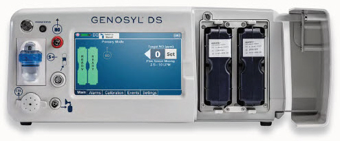
FOR DELIVERY OF
GENOSYL ®
(NITRIC OXIDE)
GAS FOR INHALATIONOPERATOR'S MANUAL
Technical Support: 877.337.4118
Company Confidential
Part No. 602502 Rev. IDO NOT COPY
VERO Biotech Inc.
387 Nerem Street NW, Suite 125
Atlanta, GA 30313 USAWARNINGS, CAUTIONS, AND NOTES
Please read all Warnings and Cautions in this Operator's Manual prior to using the GENOSYL DS.
MR Conditional Safety Information

The GENOSYL DS may be safely used in the MR environment under the following conditions. Failure to follow these conditions may result in injury.
- Maximum static magnetic field of 100 Gauss (0.01mT)
- Device remains outside the scanner bore
- Preparation protocols described in the Warnings section titled "Use in the MR Environment" must be followed before MR procedure
Image Artifacts:
When the GENOSYL DS is battery powered, no image artifacts are expected. When powered using a wall outlet, minor noise is expected.
Throughout this Operator's Manual, warnings, cautions, and notes will be displayed in the following manner.
WARNING The warning box will alert the user to possible injury, death, or serious adverse reactions associated with the use or misuse of the device. CAUTION The caution box will alert the user about proper use of the equipment and any conditions that could result in equipment damage or failure. The user should read and adhere to all warnings and cautions. NOTE The note box provides information, clarification, or supplemental information to assist and educate the user on the use of the equipment. A complete list of Warnings and Cautions for the GENOSYL DS are shown below. Where appropriate, some of these will also be shown throughout this manual.
WARNINGS Please consult the package insert for a complete list of contraindications. Alarms - ALWAYS acknowledge and follow information provided from alarms. An alarm indicates an abnormal condition, and ignoring alarms can result in possible injury, death, or serious adverse reactions.
- ALWAYS use clinical judgement when setting upper or lower alarm limits. Failure to do so could result in possible injury or death.
Consoles - ALWAYS have a second Console present and properly connected when a Dosing Console is connected to the patient. If the Dosing Console malfunctions, switch to the Back-up Console. If the Back-up Console is not available or properly connected, this may result in patient injury or death.
- DO NOT clean the GENOSYL DS with the power connected and the System turned ON, as this may lead to injury (e.g., shock). Unplug AC/DC power supply external to the System prior to cleaning.
- NEVER modify the equipment. Modifications of the equipment may result in malfunction, which may result in a fire, shock, injury, or death.
- NEVER turn the rear power switch OFF until the System has gone through a controlled shutdown or instructed by VERO Technical Support. Turning the rear power switch OFF prematurely (e.g., while it is still in use) will immediately shut down the device. This may result in interruption in NO delivery to the patient, which may cause injury or death.
Cassette - DO NOT use the Cassette if the Cassette State Window is not blue. A Cassette State Window that is any color other than blue may affect the Cassette's ability to provide the correct NO dosage to the patient, which may cause injury or death.
- DO NOT use a Cassette that is beyond its expiration date. Using an expired Cassette may affect the Cassette's ability to provide the correct NO dosage to the patient, which may cause injury or death.
- MAKE SURE the System stabilizes to the prescribed concentration (ppm) of NO prior to leaving the Console unattended. Failure to do so could result in under delivery of the target NO, leading to injury or harm.
- ALWAYS replace a Cassette once depleted. A depleted Cassette will interrupt patient dosing and can lead to underdosing and/or injury to the patient.
- ALWAYS follow Cassette inspection instructions prior to Cassette insertion. Not inspecting the Cassette prior to insertion may lead to using a faulty Cassette, resulting in injury.
Use in the MR Environment - The GENOSYL DS is classified as MR Conditional with MR scanners of 1.5 or 3.0 Tesla strength ONLY in areas where the field strength is less than 100 gauss.
- ALWAYS operate at a fringe field of less than 100 gauss. This device contains ferromagnetic components and may experience strong attraction close to the magnet.
- DO NOT exceed 100 gauss; System operation may be impacted. Confirm Cart caster lock function. Optionally connect tether.
- NEVER use the GENOSYL DS in the MR scanner room without gauss alarms installed.
- ALWAYS verify at least one gauss alarm is functioning properly prior to use in the MR environment.
- DO NOT use the GENOSYL DS in the MR environment if neither gauss alarm is functional.
- ALWAYS move System away from the MR scanner if the gauss alarm sounds. The gauss alarm will sound if the System is too close to the MR scanner. Move System away from the MR scanner until the gauss alarm stops sounding.
- ALWAYS verify that the GENOSYL DS Cart casters are locked after positioning the System in the MR scanner room.
- ALWAYS verify that the GENOSYL DS is securely attached to the Cart.
- ALWAYS arrange power cord, MR patient gas sample line, and NO delivery line to avoid entanglement, strangulation and/or a trip hazard.
- DO NOT use the GENOSYL DS in the MR environment if the Cart moves when the brake caster locks are engaged.
- NEVER perform NO or NO 2calibration within the MR scanner room. Calibration equipment is a potential projectile hazard.
Transport - ALWAYS ensure the GENOSYL DS Dosing and Back-up Consoles are securely affixed to the External Transport Mounts when the System will be used in a transport vehicle.
- ALWAYS ensure Consoles are placed into External Transport Mode before inserting a Cassette for external transport outside of the hospital.
- ONLY use External Transport Cassettes, identified by orange color and transport sticker, in external transport outside of the hospital.
- ALWAYS ensure the External Transport Mounts are secured during patient transport, per hospital protocols.
Use with Anesthesia Gas Machines - ALWAYS use the Anesthesia Gas Machine (AGM) in accordance with the manufacturer's instructions.
- The flow out of the anesthesia gas machine via the INSPIRATORY breathing circuit limb must pass through the GENOSYL DS Gas Injection Assembly.
- The GENOSYL DS injects and samples gas from the patient respiratory circuit which may affect the triggering sensitivity of the anesthesia gas machine (AGM). ALWAYS ensure the trigger sensitivity of the AGM is checked after connecting the GENOSYL DS to the breathing circuit and starting iNO delivery or when the dose is changed and adjust trigger sensitivity as necessary. Failure to do so may lead to AGM auto cycling or apnea alarm.
- ALWAYS ensure the patient disconnect and high–pressure alarms are used with the AGM.
- Ensure the Injection Assembly and the Gas Sample Tee are BOTH inserted on the inspiratory limb of the circuit.
Connections - ALWAYS follow pre-use setup instructions for the routing and connections of tubing to avoid patient strangulation.
- MAKE SURE the System has all tubing connected as described in the instructions. Not connecting all tubing may result in inaccurate dosage and harm the patient.
- NEVER touch the electrical connectors of the System or its accessories, and the patient simultaneously. If the user touches another device with a ground-fault failure and simultaneously touches the GENOSYL DS, this can result in injury (e.g., shock) should a grounding failure be present.
Battery - ONLY properly trained personnel should replace the battery. Incorrectly replacing the battery may result in a hazard such as excessive temperatures, fire, or explosion.
- MAKE SURE the GENOSYL DS is connected to AC wall power to charge the battery a minimum of once every 3 months to maintain a minimum battery charge. Failure to recharge the Console battery for extended timeframes may result in full discharge of the battery. If a Battery Error message occurs during startup of the System, contact Technical Support at 877-337-4118 for assistance.
User - ONLY intended users who are experienced in the use of this System should use this device. US federal law restricts device use to licensed medical professionals. If device is used by unintended users, device can be misused and lead to injury or death.
Alternative Means of Ventilation - ALWAYS ensure that the manual flow displayed on the Console matches the flow set into the resuscitation bag. Incorrect flow settings may result in an incorrect estimation of NO delivery. If the flow into the manual equipment is too low, there is risk of overdosing the patient with NO.
- ALWAYS squeeze the bag several times, after starting fresh gas flow, to empty residual gas in the bag prior to using the System to ventilate a patient. Failure to do so could result in higher NO 2levels being delivered to the patient.
- ALWAYS use the smallest bag adequate to deliver the desired tidal volume. Failure to do so could result in higher NO 2levels being delivered to the patient.
Patient Monitoring - ALWAYS constantly monitor the patient. System malfunctions can occur if device and patient are not monitored and can result in injury or death. Careful monitoring is required by care personnel whenever the System is used on a patient. The use of an alarm and a monitoring system does not give an absolute assurance of warning for every malfunction that may occur. Certain alarms may require immediate response.
Use with Breathing Devices - ONLY use a manual resuscitation bag with the GENOSYL DS for a short time (e.g., less than one hour) when on battery only. Otherwise, the System may shut off and may result in injury or death.
- The GENOSYL DS injects and samples gas from the patient respiratory circuit which may affect the triggering sensitivity of the ventilator. ALWAYS ensure the trigger sensitivity of the ventilator is checked after connecting the GENOSYL DS to the breathing circuit or when the dose is changed and adjust trigger sensitivity as necessary. Failure to do so may lead to ventilator auto cycling or apnea alarm.
- ALWAYS ensure the patient disconnect and high-pressure alarms are used with the ventilator.
- ONLY use the GENOSYL DS with Bio-Med Crossvent 2+ with Constant Flow ON. Not doing so may lead to elevated NO2 levels or dose variability.
Set-up - ONLY VERO Biotech authorized equipment technicians are to perform the initial System set-up prior to initial use. Failure to use an authorized equipment technician can result in a patient or user injury.
- ONLY store the GENOSYL DS as outlined in the storage instructions. Not storing the device in alignment with its storage instructions can cause the device to be unsafe and lead to injury or death.
- AVOID using the GENOSYL DS adjacent to or stacked with other equipment, as it may result in improper operation. If such use is necessary, this equipment and the other equipment should be observed to verify that they are operating normally.
- DO NOT use accessories or cables other than those specified or provided by the manufacturer of this equipment, as this may result in increased electromagnetic emissions or decreased electromagnetic immunity of this equipment and result in improper operation.
- DO NOT place portable RF communications equipment (including peripherals such as antenna cables and external antennas) closer than 30cm (12 inches) to any part of the GENOSYL DS, including cables specified. Otherwise, degradation of the performance of this equipment could occur, resulting in injury.
- Only connect to a power outlet with protective earth. Failure to connect to an outlet with protective earth may result in an electrical shock.
Troubleshooting - ALWAYS ensure patient safety before troubleshooting (such as an activated alarm) or replacing a problematic item. Not monitoring the patient prior to attending to an alarm can result in injury or death.
Calibration - ONLY use the calibration gas pressure regulators supplied by the manufacturer. Pressure regulators not supplied by the manufacturer may damage the sensors and may lead to patient injury.
- ALWAYS verify the correct NIST traceable calibration gas is being used and confirm the expiration date of the calibration gas prior to performing calibration. The use of incorrect or expired gas may result in inaccurate sensor readings and can lead to patient injury.
Cleaning and Maintenance - NEVER submerge the GENOSYL DS, Cassettes, or non-disposable Adaptive Sensor Cable. Submerging in liquids will damage the System and could cause electrical shorts which may result in injury or death.
Water Trap - ALWAYS empty Water Trap when prompted by the System, and when the trap is more than half full. Allowing the Water Trap to completely fill will occlude the Sample Line which will interrupt patient gas NO, NO 2, and O 2concentration monitoring. Failure to monitor the patient gas NO, NO 2, and O 2concentrations may result in patient injury.
- ALWAYS conduct Water Trap / Sample Line Leak Test every time you empty and replace the Water Trap, as failure to do so may lead to an incorrect NO reading, which can result in injury or death.
- ALWAYS use a Water Trap supplied by the manufacturer. Using an incorrect Water Trap could result in non-functioning or inaccurate sensor readings.
Use Outside of Product Labeling - ALWAYS use the GENOSYL DS in accordance with the indications, usage, contraindications, warnings, and precautions described in the GENOSYL prescribing information and labeling. Refer to latest approved prescribing information and labeling prior to use.
- The approved patient population for the GENOSYL DS as specified in the drug labeling for GENOSYL (nitric oxide) for inhalation, is limited to neonates. The GENOSYL DS is not intended to be used in other patient populations.
- ONLY use the GENOSYL DS, its parts, and accessories as instructed. Using non-specified components may result in product malfunction, injury, or death
- ONLY trained personnel should operate the GENOSYL DS. Failure to do so can result in injury or death.
- ONLY mechanical ventilators validated with the GENOSYL DS should be used. Not using a validated ventilator system can result in injury or harm.
CAUTIONS Supplied Instructions - ALWAYS refer to the instructions supplied with all equipment to be used in conjunction with the GENOSYL DS for their intended uses, contraindications, and potential complications. Misuse of the device or its components may damage the device.
Cassette - DO NOT remove Cassette from packaging until ready to use. External packaging is designed to protect the Cassette from damage and/or contamination.
- User should always have a secondary Cassette inserted in the Dosing Console and preheated in order for auto transition to occur. User should replace depleted Cassette as soon as possible after ejection.
Consoles - ALWAYS operate the Console on a level surface to avoid potential interruption to nitric oxide (NO) delivery.
- ONLY use recommended cleaning agents or a damp cloth to clean the Console and limit use of liquids around Console. Excess water can permanently damage the device.
- ONLY use the GENOSYL DS with the power cord supplied by the manufacturer. Use of a generic power cord may cause output voltage instability leading to a touch screen failure.
- ALWAYS ensure the power cord is firmly seated into the power supply and the wall outlet. A loose connection can result in damage to the device or faulty operation.
- Prolonged use in dry environments without humidification will damage the gas sensors. Supplemental humidification providing greater than 20% relative humidity (RH) in the patient circuit is recommended.
Use with Breathing Devices - When using spontaneous breathing modeson respiratory device, NO 2levels may exceed 3.0 ppm NO when dosing ≥ 57 ppm NO into 100% FiO 2and maximum bias flow, resulting in nitric oxide delivery interruption. Once sample value of NO 2is below 3.0 ppm, the Console will auto resume delivery of NO at set dose. Refer to Section 12.1.5 Table 13for additional information.
- When using non-spontaneous breathing modeson respiratory device NO 2levels may exceed 3.0 ppm when dosing ≥ 63 ppm NO into 100% FiO 2and maximum bias flow, resulting in nitric oxide delivery interruption. Once sample value of NO 2is below 3.0 ppm, the Console will auto resume delivery of NO at set dose. Refer to Section 12.1.5 Table 13for additional information.
Use with Anesthesia Gas Machines - The Adaptive Sensor is recommended for use with anesthesia gas machines (AGMs). When using an AGM without the Adaptive Sensor, transient dose excursions outside of the set NO dose may occur during Cassette transition, and changes in breathing circuit flow may cause fluctuations in measured levels of NO and NO 2when using the manual ventilation bag integrated with the AGM.
- When using anesthesia gas machines, NO 2levels may exceed 3.0 ppm when dosing ≥ 58 ppm NO into 100% FiO 2, resulting in nitric oxide delivery interruption. Once sample value of NO 2is below 3.0 ppm, the Console will auto resume delivery of NO at set dose.
- DO NOT use in environments with <20% relative humidity (RH) in the absence of supplemental humidification. Prolonged use in dry environments without humidification will damage the gas sensors. GENOSYL DS was validated with listed AGMs using a Heat Moisture Exchanger (HME) and was not tested with heated humidification connected to the respiratory circuit.
- Rebreathing validation testing was performed with semi-closed breathing systems. Non-rebreathing validation testing was perfumed with semi-open breathing systems. The GENOSYL DS has not been evaluated with fully open or fully closed anesthesia breathing systems.
Gas Sampling During Aerosol Delivery - Pneumatic Nebulizers will dilute the delivered nitric oxide dose.
Calibration - ALWAYS perform a full-scale calibration of the GENOSYL DS when prompted by the System prior to use.
- ALWAYS confirm the correct flow direction of the installed one-way check valve in the sampling tee to avoid over pressurization of the sample system and damage to the device.
Cleaning and Maintenance - ALWAYS follow maintenance instructions in this manual for your safety and to prevent damage to the System.
- ALWAYS power down the GENOSYL DS Console when not in use.
- DO NOT sterilize (e.g., autoclave, gas sterilize) any of the components of the System, as this may compromise performance.
- DO NOT use harsh cleaning agents. Doing so may impair the structural integrity and/or function of the device.
- DO NOT touch or rub the display screen with abrasive cleaning compounds, as they may scratch and damage the screens.
- ALWAYS ensure the System is completely dry after cleaning before powering it ON. Failure to do so could result in equipment damage.
Switching OFF the System - NEVER turn the rear power switch OFF until the System has gone through a controlled shutdown or instructed by VERO Technical Support. Turning the rear power switch OFF prematurely (e.g., while it is still in use) will immediately shut down the device and may cause improper operation upon restart.
Cart - DO NOT stand or sit on the Cart. Standing or sitting on the Cart can damage the device.
- ALWAYS push or pull the Cart using the handle only. NOT doing so may result in damage to the device.
TABLE OF CONTENTS WARNINGS, CAUTIONS, AND NOTES 3 TABLE OF CONTENTS 12 LIST OF TABLES 16 LIST OF FIGURES 17 ABBREVIATIONS, TERMINOLOGY, AND DEFINITIONS 19 SYMBOLS 21 GENOSYL DS PARTS / COMPONENTS 23 1. GENERAL INFORMATION 32 1.1 User Responsibility 32 1.2 General Information and Indications for Use 33 1.3 Principles of Operation 34 1.4 Exposure of Healthcare Providers to NO and NO 2 38 2. SYSTEM OVERVIEW 42 2.1 Frequently Used Functions 42 2.2 GENOSYL DS Cart and Consoles 43 2.3 Cassette 49 2.4 GENOSYL DS Ventilator Circuit Components 51 2.5 Gas Lines (detailed explanation) 54 2.6 Console Dosing Modes of Operation 56 2.7 Display Screen 56 2.8 Display "Menu" Tab Navigation 57 2.9 Display Screen Operational Buttons 61 2.10 Display Screen – Cassette Status Indicators 63 2.11 Display Screen - Adaptive Sensor Status 67 2.12 Cassette Insertion into Console 68 2.13 Water Trap / Sample Line Leak Test 68 2.14 Console Shutdown - Cassette Status Indicator 69 2.15 Battery Charge Status Indicator 70 3. SYSTEM SET-UP AND CONNECTIONS 74 3.1 GENOSYL DS Set-Up and Mechanical Ventilator Circuit Schematic 74 3.2 Connections to Various Breathing Systems 74 3.2.1 Conventional Ventilators 75 3.2.2 Non-Invasive Gas Delivery Systems 79 3.3 GENOSYL DS Ventilator Circuit Assembly Pre-Check 81 3.4 Assembling GENOSYL DS Injection Assembly with Adaptive Sensor and GENOSYL DS Mixer Assembly with Adaptive Sensor 83 3.4.1 GENOSYL DS Injection Assembly with Adaptive Sensor 83 3.4.2 GENOSYL DS Mixer Assembly with Adaptive Sensor 84 3.5 GENOSYL DS Console Connections 86 3.5.1 GENOSYL DS Gas Line Connections 86 3.5.2 GENOSYL DS Sample Line Extension Connection 87 3.5.3 Sample Line Filter Connection 89 3.5.4 GENOSYL DS Adaptive Sensor Cable Connection 91 3.5.5 GENOSYL DS Respiratory Circuit Connections 91 3.6 Manual Ventilation (Bag) Connection 93 3.7 Mechanical Ventilator Circuit Connections 94 3.8 Gas Sampling During Aerosol Delivery 95 4. SYSTEM START UP 100 4.1 Console Start-Up 100 4.2 Cassette Insertion & Water Trap / Sample Line Leak Test 101 4.2.1 Water Trap / Sample Line Leak Test Troubleshooting 107 5. NITRIC OXIDE ADMINISTRATION 110 5.1 Nitric Oxide Dose Set-Up and Administration 110 5.1.1 Setting a Dose when using a Circuit withan Adaptive Sensor 110 5.1.2 Setting a Dose when using a Circuit withoutan Adaptive Sensor 112 5.2 Adjusting the Dose 113 5.3 Replacement of a Depleted Cassette 115 5.4 Manual Mode 116 5.4.1 Manual Ventilation Use (Bagging) 116 5.4.2 Preset Manual Dosing Mode Flow Rate (OPTIONAL) 119 5.4.3 Resuming Primary Dosing 119 5.5 Console Use as a Back-up 120 6. CONSOLE SHUTDOWN AND CASSETTE DISPOSAL 124 6.1 Console Shutdown 124 6.2 Cassette Disposal 128 7. USING THE SYSTEM IN THE MR SCANNER ROOM 132 7.1 Connection to the Ventilator Breathing Circuit 132 7.2 Transferring to and from the MR Scanner Room 133 8. EXTERNAL TRANSPORT 138 8.1 External Transport Set-Up and Ventilator Circuit Schematics 144 8.1.1 Securing a Console in a Transport Mount 144 8.1.2 Connection to an International Bio-Med External Transport Ventilator Circuit 145 8.1.3 Connection to a Conventional External Transport Ventilator 147 8.1.3.1 Connection to a Conventional External Transport Ventilator using an Injection Assembly with Adaptive Sensor 148 8.1.3.2 Transport Ventilator Circuit Set-Up and Connections using Mixer Assembly with Adaptive Sensor 151 8.2 Using the GENOSYL DS for External Transport 153 8.2.1 Switching External Transport Mode ON 153 8.2.2 Inserting an External Transport Cassette 155 8.2.3 Setting a Dose in External Transport Mode with an Adaptive Sensor 159 8.2.4 Setting a Dose in External Transport Mode without an Adaptive Sensor 161 8.2.5 Adjusting a Dose in External Transport Mode 163 8.2.6 Using Manual Dosing Mode while External Transport Mode is Enabled 164 8.2.7 Resuming Primary Dosing while in External Transport Mode 166 8.2.8 Console Shutdown while in External Transport Mode 167 8.2.9 Switching External Transport Mode OFF 171 9. USE WITH ANESTHESIA GAS MACHINES 174 8.1 Connection to a Dual Limb Anesthesia Circuit 176 8.2 Connection Instructions for the GENOSYL DS to an Anesthesia Gas Machine 177 10. ALARMS, ALERTS, AND TROUBLESHOOTING 184 10.1 Alarms, Alerts, and Troubleshooting 184 10.2 On-screen Troubleshooting Module 186 10.3 High Priority Alarms and Messages 189 10.4 Medium Priority Alarms and Messages 200 10.5 Low Priority Alarms and Messages 204 10.6 Informational Messages 205 10.7 GaussAlert™ Alarm 207 10.8 Troubleshooting 208 10.9 Leak Detection Tool 211 11. SYSTEM MAINTENANCE 216 11.1 Calibration 216 11.1.1 Air Calibration 217 11.1.2 NO Calibration 218 11.1.3 NO 2Calibration 220 11.2 Maintenance Schedule 222 11.3 Testing the GaussAlert™ Function 222 11.4 Water Trap Maintenance 224 11.4.1 Emptying the Water Trap 224 11.4.2 Water Trap Replacement 225 11.5 Battery 225 11.6 Cleaning 226 11.6.1 Enclosure, Connections, and Surfaces Other Than the Display 226 11.6.2 Display Screen 227 11.6.3 Cleaning the Gauss Alarms Mount 227 11.7.1 Cart / Console Storage 228 11.7.2 Cassette / Accessory Storage 228 12. MECHANICAL VENTILATION 232 12.1 Mechanical Ventilation 232 12.1.1 Oxygen Dilution 232 12.1.2 Minute Volume 234 12.1.3 Trigger Sensitivity 234 12.1.4 Maximum NO Delivery 234 12.1.5 Bias Flow and NO 2 234 12.2 Ventilator Compatibility 236 13 PRODUCT SPECIFICATIONS 246 13.1 System Performance 246 13.2 System Classification 246 13.3 Testing 246 13.4 Electrical 247 13.5 Power Supply 247 13.6 Battery 247 13.6.1 Battery Charge Status Indicator 248 13.17 Display 248 13.8 Mechanical 248 13.9 Environmental 249 13.10 GaussAlert™ Specifications 249 13.11 MR Signal-to-Noise Ratio and Artifact Dimension Analysis 249 13.12 EMI/EMC 250 KEY WORD INDEX 258 LIST OF TABLES Table 1: Conventional Ventilator Compatibility Test Ranges 76 Table 2: Non-Invasive Gas Delivery System Compatibility Test Ranges 79 Table 3: External Transport Ventilation Devices Compatibility Testing Ranges 140 Table 4: External Transport Equipment Specifications 143 Table 5: Anesthesia Gas Machine Validation Compatibility Test Ranges 175 Table 6: Anesthesia Gas Machine Tidal Volume Use Cases 176 Table 7: Alarm Icon Descriptions 184 Table 8: Alarm Characteristics 185 Table 9: Alarm Ranges, Defaults and Dose Interruption Condition 185 Table 10: Alarm conditions included in On-screen Troubleshooting Module 187 Table 11: Recommended Cleaning Agents 227 Table 12: Oxygen Dilution 233 Table 13: NO Dose at which NO 2exceeded 3ppm NO 2Threshold when dosing at 100% FiO 2and Maximum bias flow 235 Table 14: Details of Validated Systems 237 Table 15: Validated Compatibility with and without Inline Mixer 241 LIST OF FIGURES Figure 1: GENOSYL DS Console Front Panel 34 Figure 2: Cassette Output Range 35 Figure 3: Calculated Time to Hospital Cassette Depletion 36 Figure 4: Calculated Time to External Transport Cassette Depletion 36 Figure 5: GENOSYL DS Assembled Cart 44 Figure 6: MR Conditional GENOSYL DS Front View 45 Figure 7: MR Conditional GENOSYL DS Side View 46 Figure 8: Front View GENOSYL DS Console 47 Figure 9: Back View GENOSYL DS Console 48 Figure 10: Right Side View GENOSYL DS Console 48 Figure 11: Left Side View GENOSYL DS Console 48 Figure 12: GENOSYL Cassette 49 Figure 13: GENOSYL External Transport Cassette 50 Figure 14: GENOSYL DS Gas Lines 55 Figure 15: GENOSYL DS Display Screen 56 Figure 16: Water Trap/Sample Line Leak Test 69 Figure 17: Conventional Ventilator Circuit Set-Up and Connections using Injection Assembly with Adaptive Sensor to the GENOSYL DS and a Manual Bagging System 77 Figure 18: Conventional Ventilator Circuit Set-Up and Connection using the Mixer Assembly with Adaptive Sensor to the GENOSYL DS and a Manual Bagging System 78 Figure 19: Fisher and Paykel Optiflow Jr 2 Breathing Circuit 79 Figure 20: Fisher and Paykel Optiflow Breathing Circuit 80 Figure 21: GENOSYL DS Injection Assembly with Adaptive Sensor 83 Figure 22: GENOSYL DS Mixer Assembly with Adaptive Sensor 84 Figure 23: MR Scanner Room 134 Figure 24: Display Navigation in External Transport Mode 139 Figure 25: GENOSYL DS on External Transport Mount 141 Figure 26: External Transport Cassette 142 Figure 27: International Bio-Med Transport Ventilator Circuit Set-Up and Connections using Injection Assembly with Adaptive Sensor to the GENOSYL DS and a Manual Bagging System 145 Figure 28: Transport Ventilator Circuit Set-Up and Connections using Injection Assembly with Adaptive Sensor to the GENOSYL DS and a Manual Bagging System 148 Figure 29: Transport Ventilator Circuit Set-Up and Connections using Mixer Assembly with Adaptive Sensor to the GENOSYL DS and a Manual Bagging System 151 Figure 30: Anesthesia Gas Machine Circuit Set-up and Connection to the GENOSYL DS without Inline Mixer 177 Figure 31: Anesthesia Gas Machine Circuit Set-up and Connection to the GENOSYL DS with Inline Mixer 177 Figure 32: On-screen Troubleshooting Menu 187 Figure 33: Description of VERO On-screen Troubleshooting Module Navigation 188 Figure 34: Screen displayed if recommended actions cannot address alarm condition, or alarm condition is active and on-screen troubleshooting support is not available 189 Figure 35: "Alarms" tab display when a leak is suspected 212 Figure 36: GaussAlert™ Test 223 Figure 37: Cassette Output Range 236 ABBREVIATIONS, TERMINOLOGY, AND DEFINITIONS ABBREVIATION / TERMINOLOGY DEFINITION Adaptive Sensor Port Port on the front of the Console that the Adaptive Sensor Cable plugs into. AGM Anesthesia Gas Machine Back-up A situation whereby the Back-up Console and its Cassette is activated in the event of a failure of the Dosing Console. Back-up Console The secondary Console used as a "Back-up" system to administer nitric oxide when the Dosing Console cannot be used. BPM Breaths per minute Cassette The Cassette contains the material used to make nitric oxide and when inserted into the Console is available for dosing the patient. cmH 20 Centimeters of water / unit of pressure Display Electronic information panel located on the front of the Console. Dosing Console The Console that is actively dosing NO. DS Delivery System Gas Sample Port Port on the front of the Console at the Water Trap that measures NO, NO 2and O 2levels within the NO gas path prior to reaching the patient. GENOSYL Nitric oxide for inhalation Hz Hertz Keypad A Graphical User Interface function built into the Console display and used to enter the nitric oxide dose to be administered to the patient. L/min Liters per minute LPM Mixer Ventilator circuit accessory used to mix the ventilator gas with the gas supplied by the GENOSYL DS for specific ventilator and tidal volume use cases, per Section 12.2. MRI Magnetic Resonance Imaging MR Scanner Bore The MR scanner opening MR Exclusion Zone Area in the MR scanner room where the magnetic field is greater than 100 gauss MR Scanner The MR device for diagnostic imaging MR Scanner Room The room where the MR scanner is located mT Millitesla; Unit used to measure magnetic field NICU Neonatal Intensive Care Unit NO Nitric oxide NO Injection Port Port on the front of the Console that introduces the concentrated NO into the respiratory circuit. NO 2 Nitrogen dioxide N 2O 4 Dinitrogen tetroxide O 2 Oxygen OD Oxygen diameter PEEP Positive end-expiratory pressure ppm Parts er Million psi Pounds per square inch/ unit of pressure System The System (GENOSYL DS) consists of a Cart with two Consoles, Cassettes, and component parts used to set up the gas lines v Electrical Volts SYMBOLS Symbol Symbol Name Description 
AC Indicates power input specification is alternating current (AC). 
Adaptive Sensor Port Input port for Adaptive Sensor Cable 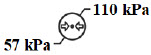
Atmospheric pressure limitation To indicate the acceptable upper and lower limits of atmospheric pressure for transport and storage. 
Attention Indicates the need for the user to consult the instructions for use for important cautionary information such as warnings and precautions that cannot, for a variety of reasons, be presented on the medical device itself. 
Batch Code Indicates the batch code so that the batch or lot can be identified. 
Calibration Port Input port for calibration gas 
Catalog or model number Indicates the catalog number so that the medical device can be identified. 
Consult instructions for use Informs the user to consult the instructions for use. 
Date of Manufacture Indicates the date when the medical device was manufactured. 
Do not reuse Indicates a medical device that is intended for one use, or for use on a single patient during a single procedure. 
External Transport Symbols Appears on External Transport Cassettes to indicate Cassette can be used during patient transfer in rescue vehicle, fixed wing, or helicopter. 
Ingression Code for the level of ingression protection tested. The enclosure was tested to be drip proof. 
Magnetic Resonance (MR) Conditional Indicates that the System has been demonstrated to pose no known hazards in a specified MRI environment with specified conditions of use. 
Manual Ventilation Output port for GENOSYL to manual ventilation system 
Manufacturer Indicates the manufacturer of the item. 
NO Injection Output port for GENOSYL to patient circuit 
Operating Instructions Refer to operating instructions for instructions for use, warnings, precautions, and other equipment information. 
RF Interference Devices marked with this symbol may interfere with the Console. 
Sample Gas Inlet Attachment point for Sample Line on Water Trap 
Serial Number Indicates the serial number so that a specific medical device can be identified. 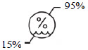
Storage humidity range Indicates the range of humidity to which the medical device can be safely exposed. 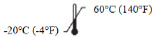
Storage temperature range Indicates the temperature limits to which the medical device can be safely exposed. 
Unlock position Direction to push to open the Water Trap. 
Use by Indicates the date after which the medical device is not to be used. 
Water Trap Attachment Point Indicates the location where the Water Trap with Sample Port is to be attached. GENOSYL DS PARTS / COMPONENTS PART PART NAME 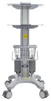
GENOSYL DS Cart 
GENOSYL DS Console
(2 required per System)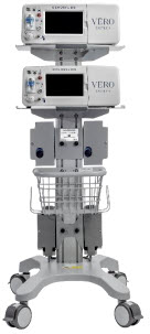
MR Conditional GENOSYL DS System 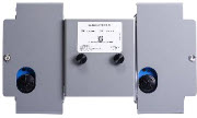
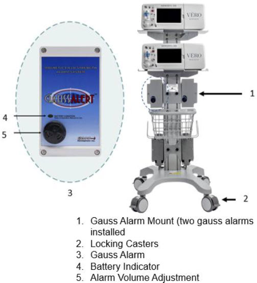
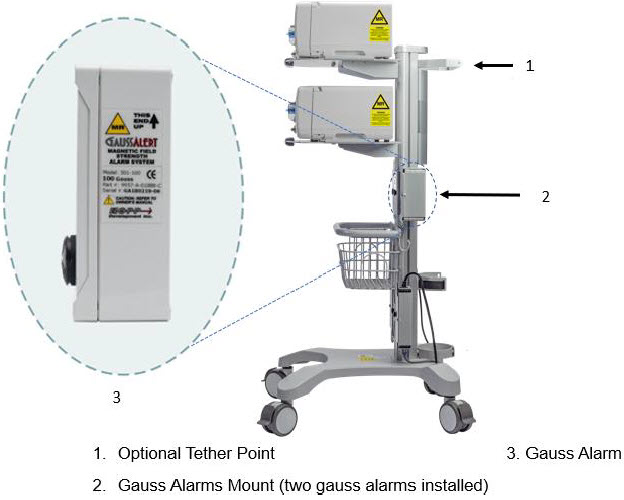
Gauss Alarms Mount
(2 gauss alarms installed)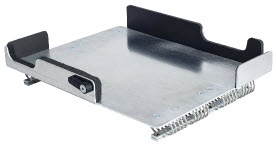
External Transport Mount 
External Transport Mount with Quick Connect Plate 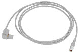
Adaptive Sensor Cable The following parts are required to set up the GENOSYL DS and deliver nitric oxide to the patient breathing circuit, using validated ventilators, ventilator circuits, and manual ventilation equipment.
PART PART NAME 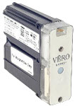
GENOSYL Hospital Cassette
(may be referred to as Cassette or Hospital Cassette)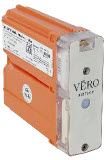
GENOSYL External Transport Cassette
(may be referred to as Cassette or External Transport Cassette)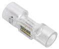
Adaptive Sensor 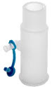
NO Gas Injection Adapter
22M/15F × 22F
Adapter
22F × 22F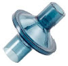
Inline Breathing Circuit Filter . 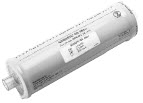
GENOSYL DS Mixer 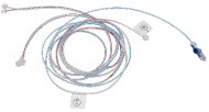
GENOSYL DS Gas Lines:
NO Injection Line (red)
Sample Line (blue)
Manual Ventilation Line (clear)
GENOSYL DS Sample Line Extension 
Neonatal Gas Sample Tee 
Water Trap 
22M 22F Elbow Adapter 
Sample Line Filter 
Sample Tee, 3/8" Barbed 
Injection Line Filter 
22M/15F × 22M/15F Adapter 
15M × 4.5 Adapter 
22M/15F × 15M Gas Sample Tee 
22F × 15M Adapter Note: Physical appearances may vary slightly.
The following parts are required to deliver nitric oxide using a manual ventilation system.
PART PART NAME 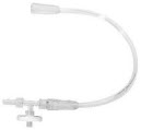
GENOSYL DS Manual Ventilation Bag NO Adapter Note: Physical appearances may vary slightly.
The following parts are required for routine maintenance.
PART PART NAME 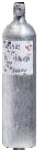
Calibration Gas - 45 ppm NO 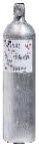
Calibration Gas - 10 ppm NO 2 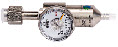
Calibration Regulator 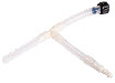
Calibration Tee Tubing 
Calibration Extension Tubing 
Calibration Gas Carrying Case 
Calibration Equipment Wrench 
Calibration Regulator Teflon Washer Note: Physical appearances may vary slightly.
GENOSYL ®DS
SECTION 1
GENERAL INFORMATIONThe GENOSYL DS (Console) will perform as described in this Operator's Manual, accompanying inserts, and/or labels when assembled, operated, maintained, and repaired in accordance with the instructions provided. The Console must be set up as described in Section 3. If the Console does not perform as described in Section 3or during assembly, the parts are found to be broken, missing, contaminated, or visibly worn, they should be replaced immediately.
In the case of repair or replacement of the Console is required, a telephone service request should be made to Technical Support at 877-337-4118.The GENOSYL DS or any of its parts should not be serviced or repaired by anyone other than a VERO Biotech Technical Engineer or without written permission from VERO Biotech Technical Engineering Department.
Any malfunction resulting from faulty maintenance, improper repair, damage, alteration by anyone other than a VERO Biotech Technical Engineer, and/or improper use will be the sole responsibility of the User.
WARNING The GENOSYL DS must only be used in accordance with the approved indications, usage, contraindications, precautions, and warnings described in the GENOSYL DS labeling. Refer to the labeling prior to use. CAUTION U.S. Federal law restricts this device to sale by or on the order of a physician. Outside the U.S., check local laws for any restrictions that may apply. NOTES - Prior to using the GENOSYL DS, read through this Operator's Manual.
- Follow all instructions and obey the Warnings and Cautions.
- Keep this Operator's Manual available to readily answer questions.
- Read through all manufacturer Operator's Manuals for the ventilator, humidifier and any other accessory items used.
1.2 General Information and Indications for Use
GENOSYL DS generates and delivers NO for inhalation at the point of use. The concentration of NO, as set by the user, is monitored, and adjusted to accurately dose the patient throughout an inspired breath. Only validated devices / components should be used with the GENOSYL DS.
The intended population for inhaled NO treatment is term and near-term neonates in neonatal intensive care units (NICUs). Refer to the GENOSYL (nitric oxide) for inhalation drug label for more detailed information.
The GENOSYL DS is intended for use in the hospital, 1.5 Tesla and 3.0 Tesla diagnostic imaging environments, during patient transfer via rescue vehicle, fixed wing aircraft, or helicopter, and the operating room in conjunction with validated anesthesia gas machines.
The GENOSYL DS is intended for use by healthcare professionals (HCPs) who are licensed and actively practicing pediatric and/or neonatal respiratory therapists (RTs), or HCPs in the operating room with the supervision of RTs in the United States. These users are required to set up, administer inhaled nitric oxide (iNO) and provide respiratory care (including initiation and maintenance of mechanical ventilators) in the critically ill neonatal population.
The GENOSYL DS starts with liquid N 2O 4/NO 2, which is then converted in a proprietary Cassette to NO. The GENOSYL DS delivers NO into the ventilator stream, where the NO joins a stream of air or O 2and is diluted to the prescribed concentration.
The NO concentration (dose) to be delivered to the patient is selected by the user and is set and maintained independently by means of computer-controlled air pumps, Cassette heaters, and a feedback loop that measures the delivered NO concentration.
The GENOSYL DS takes a gas sample removed from the NO gas flow stream immediately prior to the patient and provides real-time output of the NO, NO 2, and O 2concentrations that are being delivered to the patient. The continuous integrated gas monitoring includes a comprehensive alarm system.
The NO concentration detected from the sample line is used in a feedback loop to adjust the NO concentration delivered into the ventilator circuit.
The GENOSYL DS includes a redundant Console for complete back-up capability for delivery of NO for inhalation. Each Console has a back-up battery that is expected to last up to four hours under optimal conditions in the absence of an external power source. Console will alarm when less than 15 minutes of battery life remains.
GENOSYL DS. The GENOSYL DS continuously introduces a precisely controlled concentration of nitric oxide (NO) into the inspiratory limb of the ventilator circuit. GENOSYL DS utilizes the known properties of NO and other oxides of nitrogen, namely dinitrogen tetroxide (N 2O 4) and nitrogen dioxide (NO 2), to create a "tankless" drug/device combination System to produce, at the point of use, ultra-high purity NO for inhalation, providing a consistent, prescribed dose to the patient.
Console.The GENOSYL DS Console contains the electronics to control the production and to maintain the constant and precise delivery of NO.
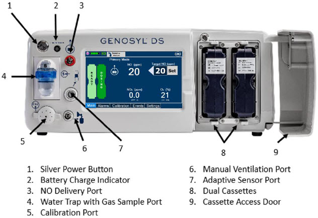
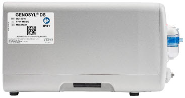
The primary features of the Console front panel are displayed in Figure 1.
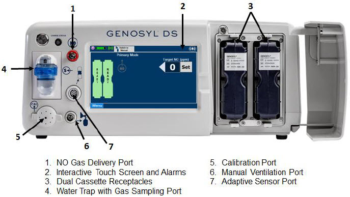
NO generation.The Console uses Cassettes containing liquid N 2O 4/NO 2inside a stainless-steel vessel (the liquid module) and an antioxidant cartridge. Upon initiation of a Cassette, the liquid N 2O 4is heated, producing NO 2gas, which is mixed with up to 0.9 LPM ambient air supplied by the Console. The NO 2/air is injected into the antioxidant cartridge inside the Cassette, which converts NO 2to NO.
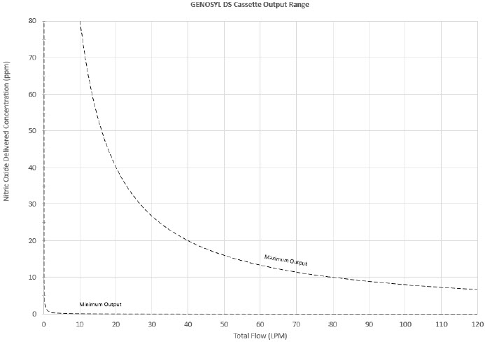
The Cassette is designed to provide NO in concentrations up to 80 ppm. The maximum and minimum delivered dose for a range of constant inspiratory flow rates is presented in Figure 2.
The maximum combination of dose (ppm) and flow (LPM) output of the System is 800 ppm × LPM (e.g., 20 ppm with 40 LPM, 40 ppm at 20 LPM, etc.). The System is capable of delivering NO at a minimum of 1 ppm × LPM (e.g., 1 ppm at 1 LPM).
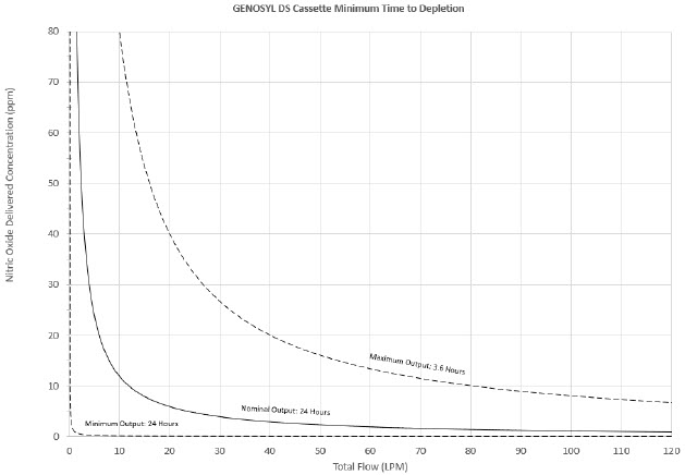
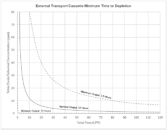
The total time to deplete the Cassette N 2O 4contents depends on the rate of use. The minimum time to depletion based on use rate for Hospital Cassettes is shown in Figure 3.The minimum time to depletion of the External Transport Cassette based on use rate is shown in Figure 4.The calculated minimum remaining contents at the current output rate is indicated by a gauge presented on the Console display during use.
NO Injection into the Ventilator Circuit. After NO is produced in the Cassette, the NO injector introduces the concentrated NO into the ventilator circuit where the NO is diluted to the prescribed concentration (dose) and mixed with the O 2or air supplied to the patient.
GENOSYL Smart Feedback System ™Before the gas mixture reaches the patient, a sample line removes a small gas sample and sends it back to the Console, where gas sensors continuously measure the supplied NO, NO 2and O2. The Console software then compares the measured NO concentration to the set NO concentration and continuously adjusts the delivery of NO to maintain the prescribed NO concentration (dose) delivered to the patient (closed loop control). The Console software commands the NO injection flow rate into the ventilator circuit with a maximum flow rate of 0.9 LPM. Changes in the ventilator settings by the user may cause brief transient changes in the measured NO value. The Console software will adjust the injected flow rate and the internal temperature of the Cassette to compensate for the changes in the total ventilator flow rate. For example, a higher minute ventilation will require a higher injection flow rate to produce the same NO concentration.
Mixer. An inline Mixer is used in the applicable ventilator circuit after the NO injection site and before the gas sample site to mix NO from the Console with the gas supplied by the ventilator, for specific ventilator and tidal volume use cases per Section 12.2.
Gas Monitoring.The gas mixture delivered to the patient by the GENOSYL DS is continuously monitored with two NO detectors, with one providing redundant back-up, as well as a detector for NO 2and O 2. A sample of inspired gas is taken from the inspiratory limb, close to the patient, and is measured by the gas sensor within the Console. The gas monitoring sensors are electrochemical; they are specific to each gas and provide an electronic signal that is proportional to the concentration of gas present.
Adaptive Sensor.The Adaptive Sensor is used to detect flow in the patient breathing circuit. When flow is not detected by the Adaptive Sensor, nitric oxide delivery will be interrupted until flow is detected. The Console will provide a visual and audible low priority alarm when flow is not detected to alert the user (see Section 10.5). Once flow is detected, the Console will auto resume delivery of nitric oxide at the previously set dose. An Adaptive Sensor is recommended for use with certain breathing devices. Refer to Section 3for recommended set up diagrams. The GENOSYL DS will properly deliver and control nitric oxide dose in the absence of an Adaptive Sensor.
Alarms and Dosing Safeguard Fallback Modes.The GENOSYL DS alerts the user in the event of excursions of NO, NO 2, and Oxygen from their expected ranges. Nitric oxide delivery interruption conditions are as follows:
- NO > 100 ppm
- NO 2reaches 3 ppm
- The measured respiratory circuit dilution flow drops below 0.3 LPM as measured by the Adaptive Sensor.
The Console will provide a visual and audible high priority alarm. When detecting a sustained gas level higher than the above limits for 11 consecutive seconds, the Console will interrupt delivery of NO until the sampled levels of NO and/or NO 2decrease to a safe level. Once sampled levels are in acceptable range, the Console will resume delivery with previously set dose.
If the cause of the high gas cannot be resolved, the use of the Back-up Console may be required. Refer to Section 10.1for additional information on alarms and dosing safeguards.
If NO delivery was interrupted due to the GENOSYL DS Adaptive Sensor reading dropping below 0.3 LPM, the Console will resume delivery with the previously set dose once the Adaptive Sensor reading exceeds 0.35 LPM. The automatic resumption of dose delivery after the interruption conditions listed above are cleared is one of the safety fallback modes of the GENOSYL DS.
Back-up NO Delivery.The Back-up Console is used to administer nitric oxide when the Dosing Console cannot be used. This Console has a separate power supply, and at least one Cassette loaded and preheated. If the Dosing Console fails to deliver NO, the Back-up Console is ready to begin dosing to continue NO delivery.
Transition to a new Cassette.When a Cassette approaches depletion, the Dosing Console will automatically transition to the second Cassette in the Console. Once the dosing Cassette is depleted, the Dosing Console will eject the depleted Cassette and alert the user to replace via the Cassette Status Indicator.
Disposal of the Cassette. Following use, any remaining Cassette contents are purged into an inerting chamber, where the contents are chemically neutralized, rendering the Cassette safe for disposal.
1.4 Exposure of Healthcare Providers to NO and NO 2
Occupational exposure of healthcare providers to NO or NO 2may occur during Inhaled NO therapy for patients. Below are examples of calculated and observed exposure to NO or NO 2, in the context of guideline workplace exposure limits.
Calculated and observational methods show that the exposure levels to NO or NO 2from an NO delivery system are significantly less than the levels recommended by the National Institute for Occupational Safety and Health (NIOSH).
Workplace Limits: NIOSH has recommended workplace exposure limits as follows 1.
NO time-weighted (8 hours) average concentration limit of 25 ppm NO 2 Recommended exposure limit of 1 ppm Theoretical Calculation.The build-up of NO in a well-ventilated ICU room, with NO flowing directly into the room, can be evaluated using the following calculation:
Room size 1000 ft 3 Room volume 28,300 L Room ventilation (6 complete exchanges/hour) 2,830 L/min NO flow into the room 80 ppm at 14 L/min Average NO room concentration 0.4 ppm of NO Observations of NO Exposure. The theoretical calculation has been supplemented by actual measurements in three independent studies in actual therapeutic use settings. 2,3,4The studies found that detectable exposures to NO and NO 2were brief, infrequent, and well below recommended exposure limits.
If the location for using NO has uncertain ventilation, then the location should be evaluated for NO and NO 2build-up prior to use.
GENOSYL ®DS
SECTION 2
SYSTEM OVERVIEWDetailed instructions are provided in this manual for the primary user interaction and frequently used functions of the GENOSYL DS, which include:
System Set-Up and Connections (Section 3)
- Connections to Various Breathing Systems
- GENOSYL DS Ventilator Circuit Assembly Pre-Check
- GENOSYL DS Injection Assembly with Adaptive Sensor
- GENOSYL DS Mixer Assembly with Adaptive Sensor
- GENOSYL DS Console Connections
- GENOSYL DS Gas Line Connections
- GENOSYL DS Sample Line Extension Connection
- GENOSYL DS Adaptive Sensor Cable Connection
- GENOSYL DS Ventilator Circuit Connection
- GENOSYL DS Manual Ventilation Connections
- GENOSYL DS Mechanical Ventilator Circuit Connections
- Gas Sampling During Aerosol Delivery
System Start-Up (Section 4)
- Console Start-Up
- Cassette Insertion
- Water Trap / Sample Line Leak Test
Nitric Oxide Administration (Section 5)
- Setting a Dose when using a Circuit with an Adaptive Sensor
- Setting a Dose when using a Circuit without an Adaptive Sensor
- Adjusting the Dose
- Manual Dosing Mode
- Manual Ventilation Use (Bagging)
- Preset Manual Dosing Mode Flow Rate (Optional)
- Resuming Primary Dosing
- Console Use as Back-up
Console Shutdown (Section 6)
- Console Shutdown
- Cassette Removal
- Cassette Disposal
Using the System in the MR Scanner Room (Section 7)
- Connection to the Ventilator Circuit
- Transferring to and from the MR Scanner Room
External Transport (Section 8)
- External Transport Set-up and Ventilator Circuit Schematics
- Using GENOSYL DS for External Transport
Use with an Anesthesia Gas Machine (Section 9)
- Connection to a Dual Limb Anesthesia Circuit
- Connection instructions for the GENOSYL DS to an Anesthesia Gas Machine
Alarms, Alerts, and Troubleshooting (Section 10)
- On-Screen Troubleshooting Module
- Alarms (High, Medium, and Low Priority)
- Informational messages
- GaussAlert™ Alarm
- Troubleshooting
- Leak Detection Tool
System Maintenance (Section 11)
- Calibration
- Maintenance Schedule
- Testing the GaussAlert™ Function
- Water Trap Maintenance
- Battery
- Cleaning
- Storage
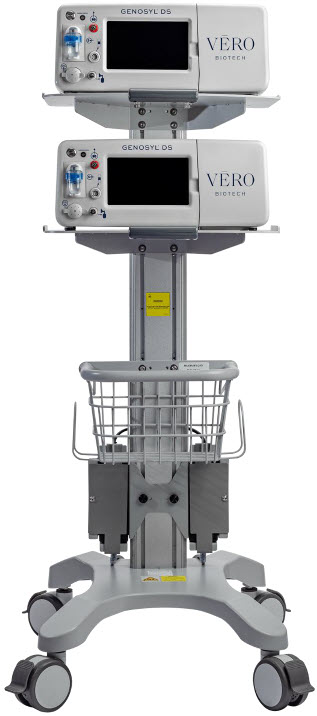
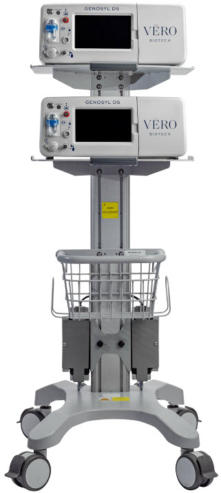
2.2 GENOSYL DS Cart and Consoles
The following pages contain photos of the GENOSYL DS Consoles. The specific sections of the GENOSYL DS are numbered with the respective description listed below the photo.
WARNING - NEVER use the MR Unsafe GENOSYL DS Cart in the MR scanner room.
- ALWAYS verify at least one gauss alarm is functioning properly prior to use in the MR environment.
CAUTION - ALWAYS operate the Console on a level surface to avoid potential interruption to nitric oxide (NO) delivery.
- DO NOT stand or sit on the Cart. Standing or sitting on the Cart can damage device.
- ALWAYS push or pull the Cart using the handle only. NOT doing so may result in damage to the device.
NOTE A System has a top and bottom Console. Both Consoles will start-up in Primary Dosing Mode. One Console will be used for dosing and the other will remain in Primary Dosing Mode as a Back-up Console. (SeeSection 5.5) 

The Cassette contains the material that will be converted to nitric oxide during the activation process. It is inserted into the GENOSYL DS Console, and its shape helps ensure proper orientation during the insertion process. A Cassette State Window is located on the front of the Cassette to indicate if the Cassette is available for use (blue), or if it has been inerted and unavailable for use (bleached and reddened).
The GENOSYL DS requires different Cassettes for use in the hospital (ICU or MR setting of care) and for use in external patient transport. The Hospital Cassette is blue in color. See Figure 12for details about the Hospital Cassette. The External Transport Cassette is orange in color. Refer to Section 8for more information about using the GENOSYL DS in external transport and Figure 13for details about the External Transport Cassette.
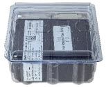
Cassette in Packaging
Unused Cassette
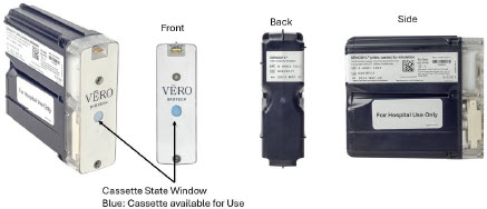
Inerted Cassette

Figure 12: GENOSYL Cassette External Transport Cassette in Packaging

Unused External Transport Cassette
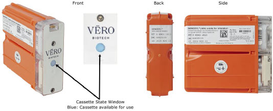
Inerted External Transport Cassette

Figure 13: GENOSYL External Transport Cassette CAUTION DO NOT remove Cassette from packaging until ready to use. External packaging is designed to protect the Cassette from damage and/or contamination. 2.4 GENOSYL DS Ventilator Circuit Components
The following parts are used to set up the GENOSYL DS portion of the patient respiratory circuit, as specified in Section 3.2.
PART PART NAME FUNCTION 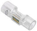
Adaptive Sensor Used to measure flow from the ventilator into the circuit. 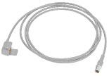
Adaptive Sensor Cable Used to communicate flow readings to the Console. 

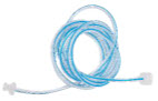
GENOSYL DS Gas Lines
NO Injection Line (red)
Sample Line (blue)
NO Manual Ventilation Line (clear)Used to deliver nitric oxide to the ventilator circuit and manual ventilation bag, and to sample gas within the ventilator circuit. 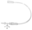
GENOSYL DS Manual Ventilation Bag NO Adapter Used to connect oxygen tubing to manual ventilation bagging system to deliver nitric oxide. Includes an NO Injection Port to connect to the NO Injection Line. 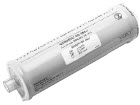
GENOSYL DS Mixer Used to mix the NO gas with the gas supplied by the ventilator through a filter containing silica gel to provide intra-breath NO delivery for certain scenarios. 
Adapter
22F × 22FUsed as a coupler between the Mixer and the Gas Injection Adapter when a Mixer is required. 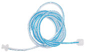
GENOSYL DS Sample Line Extension Used when the distance between the patient and the DS exceeds the length of the standard sample gas line in the MR Environment. 
Injection Line Filter Used to filter air from the Injection Line. 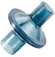
Inline Breathing Circuit Filter Used to filter air from the Injection Line, and on the expiratory limb when used with an anesthesia gas machine. 
Neonatal Gas Sample Tee Used to connect the Sample Line to the ventilator circuit. 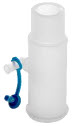
NO Gas Injection Adapter
22M/15F × 22FUsed between the Adaptive Sensor and the Inline Breathing Circuit Filter, and to connect to the NO Injection Line (red). 
Sample Tee, 3/8" Barbed Used to accommodate gas sampling in some ventilator circuits, (e.g., Crossvent Infant Circuit). 
Sample Line Filter Used to protect sampling system during use with aerosol medications (refer to Section 3.8). 
Water Trap Used to protect sample system by collecting condensation and filtering contaminants from the sampled gas. The Water Trap may need to be emptied or changed while in use (refer to Section 11.4). 
22M/15F × 22M/15F Adapter Used to create GENOSYL DS sampling port 6 to 12 inches from the patient wye. 
15M × 4.5 Adapter Used between Oxygen Tubing and NO Gas Injection Adapter with some non-invasive gas delivery systems. 
22M/15F × 15M Gas Sample Tee Used to connect the Sample Line to the ventilator circuit. 
22F × 15M Adapter Used to assist with connection of the NO Delivery Injection Assembly to various ventilator circuits. 2.5 Gas Lines (detailed explanation)
Gas lines are used to deliver nitric oxide from the GENOSYL DS Consoles to the ventilator circuit and manual ventilation bag, and to sample gas within the ventilator circuit. The lines are color coded and labeled with icons corresponding to colors and icons on each Console.
The NO Injection Line (red) delivers nitric oxide from the Console to the mechanical ventilation circuit (described in Section 3.5).
The Sample Line (blue) also contains a stopcock to conduct the Water Trap / Sample Line Leak Test (described in Section 4.2).
A Sample Line Extension is available when additional distance between the patient circuit and the Console is required (e.g., use in the MR environment) (described in Section 3.5.2).
The Manual Ventilation Line (clear) delivers nitric oxide from the Console to the Manual Ventilation Bag NO adapter (described in Section 3.6).


2.6 Console Dosing Modes of Operation
During operation, a Console can be in one of two dosing modes; Primary Dosing Modeor Manual Dosing Mode. The user can switch the dosing modes during normal operation to perform specific functions for certain conditions. The following table summarizes key characteristics of each dosing mode. Both dosing modes are available when External Transport is ON and when External Transport is OFF.
MODE FUNCTIONAL CHARACTERISTICS Primary Dosing - The dosing mode of operation for controlled dosing with Smart Feedback System™.
Manual Dosing - The dosing mode of operation used for manual ventilation.
- Manually adjustable fixed dosing without the need of feedback for certain conditions.
The GENOSYL DS display screen is presented below ( Figure 15) followed by a table with descriptive text corresponding to the numbers shown around the display screen.
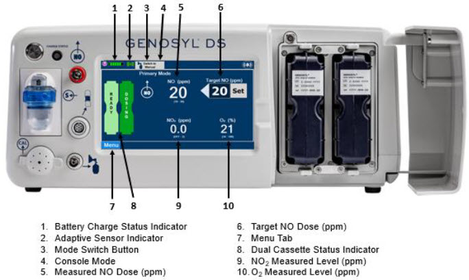
NOTE Some confirmation display screens (e.g., "Confirm", "Yes", "Accept", etc.) will be semi-transparent after dosing has been initiated to allow the Operator to continue to see important information on the underlying screen (e.g., NO values, Alarms, Alerts, etc.). 2.8 Display "Menu" Tab Navigation
The table below consists of the available "Menu" tabs (Main, Alarms, Calibration, Events, and Settings) along with the functional description of each tab, and the buttons within each tab. When regular night (dark) display view is used and a tab is selected, the title of the tab will appear on a bright blue background. When the tab is not selected, it will appear with a dark blue background. When day (light) display view is used, and a tab is selected, the tab will appear on a bright blue background. When the tab is not selected, it will appear on a light blue background. When External Transport Mode is ON, the tab currently selected will have an orange background and tabs not actively selected will have a blue background.
MENU TAB DISPLAY TAB / BUTTON DESCRIPTION 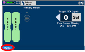

Press this tab to access the sub-level tabs (Main, Alarms, Calibration, Events, and Settings). 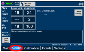

Displayed when the "Alarms" tab is selected, this screen is used to set the Upper and Lower Alarm Limits for NO (ppm), NO 2(ppm), and O 2(%).
A list of Alarms that have occurred since the last reset for the Console will be displayed on this tab.NOTE See Section 10for additional information on alarms and alerts. 
Displayed after pressing the "Alarms" tab, press this button to switch to the default upper and lower limits for NO (ppm), NO 2(ppm), and O 2(%). 
Pressing this button will clear the alarm history from the alarm log visible on this tab. The alarm will remain logged in the Console's permanent logs. 
Press this tab to return to the main screen. Pressing the Main Tab will collapse the tab menu. 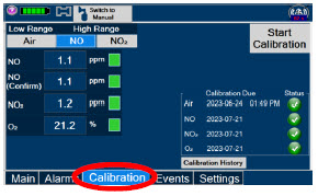

Press this tab to access the calibration screen. NOTE See Section 11.1for additional information on Calibration. 
Press this button to calibrate the low range of the NO and NO 2sensor. 
Press this button to calibrate the high range for the NO sensor. 
Press this button to calibrate the high range for the NO 2sensor. 
Press this button to initiate calibration for the selected gas. 
Press this button to stop the calibration in the middle of a calibration process. The previous calibration will remain to be used. 
Press this button to display the history of calibration. 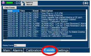

Press this tab to access the events menu. 
Press this button to clear the events listed on the events screen. 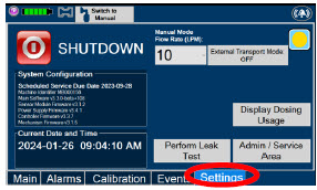
Press this tab to access the settings screen. 
Press this button to begin the process of shutting down the Console. 
Press this button to switch display to day (light) display view. This will switch the display to a lighter gray background instead of the dark blue background. 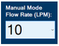
This drop-down menu allows operator to preset the dilution flow rate for Manual Mode. If no rate is selected, Console will default to 10 LPM. 
Press this button to enter the screen to adjust the date and time. This button is only present when logged in as an Administrator 
Press this button to adjust the date and time. This button is only present when logged in as an Administrator 
Press this button to perform a "Water Trap/ Sample Line Leak Test". 
Used by service personnel only. Password controlled. NOTE Contact Technical Support at 877-337-4118for additional support. 
Press this button to display a window to enter date ranges to retrieve dosing usage over a period of time and number of Cassette activations. 
Press this button to enable External Transport Mode. This button is gray when External Transport Mode is OFF. NOTE This will require the transport PIN. Contact Technical Support for additional support. 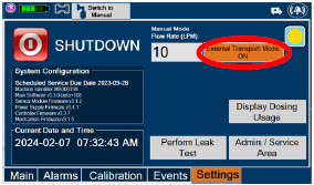
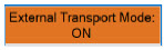
Press this button to disable External Transport Mode. This button is orange when External Transport Mode is ON. NOTE This will require the transport PIN. Contact Technical Support for additional support. 
When External Transport Mode is ON, the External Transport animated icons will rotate between these three icons in the upper right corner of the screen next to the Alarm icon. 

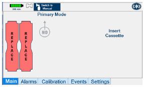

Day (Light) display view Main Menu: Press this tab to access the sub-level tabs (Main, Alarms, Calibration, Events, and Settings). 
Press this button to switch display to regular night (dark) display view. This button is located on the "Settings" tab. 2.9 Display Screen Operational Buttons
The following buttons on the display screens allow the Operator to operate and adjust the GENOSYL DS prior to and during the delivery of nitric oxide.
Note: the following are shown in regular night (dark) display view but are also available in day (light) display view.
BUTTON DESCRIPTION 
Press this button to set the targeted NO (ppm) dose when in Primary Dosing Mode. 

Press this button to pre-silence alarms. Pushing this button will pre-silence specific alarms for 120 seconds.
When active, a red "X" will appear through the alarm icon with a countdown of how much longer alarms will be pre-silenced for. When tapping the icon with the red "X", the user will cancel the pre-silence.
Press this button to cancel the Water Trap / Sample Line Leak Test. 
Press this button to switch a Console to Primary Dosing Mode from Manual Dosing Mode.
When in Primary Dosing Mode, the dosage can be set to a user selected (prescribed) level.
Press this button to switch from Primary Dosing Mode to Manual Dosing Mode.
See Section 5.4for information about dosing in Manual Dosing Mode.
Electronic keypad used to set and adjust the prescribed targeted nitric oxide dose to be delivered to the patient. Includes buttons to confirm "OK", "Cancel", or "Clear" the entry. 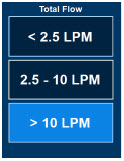
The Total Flow range is selected by the user if the Adaptive Sensor is not connected to the Console. These buttons will only appear if the Console does not detect an Adaptive Sensor when setting or adjusting dose.
Total Flow range is the sum of the ventilator (or ancillary equipment) Bias Flow and the minute ventilation of the patient.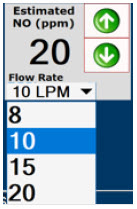
Displayed when in Manual Dosing Mode, press the green up or down arrows to adjust the dose to the patient, from the default dose.
Pressing the down arrow will decrease the dose in increments of 1 ppm for 24 ppm and below. Pressing the up arrow will increase the dose in increments of 2 ppm above 24 ppm.
Press the green LPM (liters per minute) button to activate a drop-down menu and set a different dilution flow rate.
Press this button to confirm the action specified on the screen. 
Press this button to cancel the action specified on the screen. 
Press this button to acknowledge the information message displayed on the screen. 
Press this button to move to the next step. 
Press this button to cancel the current step. 2.10 Display Screen – Cassette Status Indicators
The following describes the Cassette Status Indicators that will be shown on the display screen prior to, during, and post-delivery of nitric oxide. The Cassette Status Indicators consist of two Cassette icons, which correspond to the left and right Cassette receptacles.
CASSETTE STATUS
INDICATOR DISPLAYDESCRIPTION 
This Cassette Status Indicator will be displayed when a Cassette is not loaded into the Console. The Cassette Status Indicator will display "REPLACE" and will alternate between a dark red and light red.
The user is prompted to "Replace"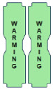
This Cassette Status Indicator is displayed during the warmup phase when a new Cassette is inserted. This indicator will display "WARMING" alternating with "READY". Dose may be initiated while the Cassette is warming. 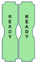
This Cassette Status Indicator is displayed once the Cassette has achieved a fully preheated status. 

This Cassette Status Indicator is displayed during dosing.
If a secondary Cassette has been inserted, the Cassette Status Indicator will display "Dosing" for the dosing Cassette and "Ready" for the secondary Cassette.
If a secondary Cassette has not been inserted, the Cassette Status Indicator will display the percentage of nitric oxide remaining in the dosing Cassette and the secondary Cassette Status Indicator will be red and display "Replace". A low priority tone will also sound in ten second intervals until a secondary Cassette is inserted.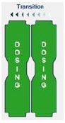
This Cassette Status Indicator will be displayed when the Console is transitioning from the dosing Cassette to the secondary Cassette. The direction of the arrow indicates the Cassette that is being transitioned to. 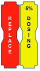
This Cassette Status Indicator will be displayed when less than one hour of Cassette life remains and no secondary Cassette is inserted. The indicator will display the percentage of life remaining in the dosing Cassette and the estimated time before depletion.
The Cassette Status Indicator for the dosing Cassette will appear yellow and display "Dosing" and the other Cassette Status Indicator will appear red and display "Replace"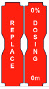
This Cassette Status Indicator is displayed when a Cassette is depleted and no secondary Cassette is inserted in the Console. This status will only display if another Cassette is not present in the Console.
The Cassette Status Indicator for the dosing Cassette will appear red and display "Dosing 0%" and "0m". The empty Cassette Status Indicator will appear red and display "Replace". Both indicators will alternate between a dark and light red color.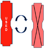
This Cassette Status Indicator will be displayed when a Cassette that has previously been used is inserted in a Console. The Cassette display will alternate between "USED" and an "X" through the Cassette icon. The Console will automatically eject a previously used Cassette. 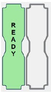
This Cassette Status Indicator will be displayed two minutes after inserting one Cassette into the Back-up Console. The secondary Cassette Status Indicator on the screen will switch from a red flashing "REPLACE" to an empty gray Cassette outline.
Once a dose is entered, and the inserted Cassette is activated, the outline will switch back to the red flashing "REPLACE" so the user is prompted to insert a secondary Cassette in the dosing Console.
This Cassette Status Indicator is displayed when a Cassette is non-operational. A white X will appear over a red Cassette Status Indicator. The Console will eject a non-operational Cassette and dose from the secondary Cassette, if properly inserted. User will be prompted to replace Cassette after ejection. 
This Cassette Status Indicator is displayed when a Cassette is past its expiration date. The display will read "EXPIRED". An expired Cassette cannot be used for dosing and will be automatically ejected from the Console. User will then be prompted to replace the ejected Cassette via the Cassette Status Indicator. 
This Cassette Status Indicator will be displayed when the wrong Cassette type is inserted into the Console. The display will read "WRONG TYPE" then proceed to eject the incorrect Cassette from the Console.
A Hospital Cassette will be ejected while External Transport Mode is turned ON and an External Transport Cassette will be ejected while External Transport Mode is turned OFF.2.11 Display Screen - Adaptive Sensor Status
The following describes the Adaptive Sensor status that will be shown on the display screen. The Adaptive Sensor Icon is located on the top left of the Console display screen. To troubleshoot the Adaptive Sensor, see Section 10.8 Troubleshooting.
ADAPTIVE SENSOR DISPLAY DESCRIPTION 
The Console has detected flow through the Adaptive Sensor. 
The Console has detected an Adaptive Sensor without flow.
To initiate delivery, the Console requires flow detection. The Set button will not appear until flow is detected through the Adaptive Sensor. The screen will appear as pictured below. Once flow is detected, the "Set" button will appear and allow the user to set the dose.
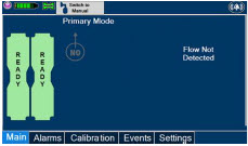
If the Adaptive Sensor stops detecting flow while dosing, the Console will interrupt delivery of NO into the circuit and display a turquoise "Flow Not Detected-Nitric Oxide Delivery Interrupted" message. This message will be accompanied by a low tone every 10 seconds. See Section 10.5 Low Priority Alarms and Messages.
The Console does not detect an Adaptive Sensor is connected 
An Adaptive Sensor is detected but the Adaptive Sensor is either malfunctioning or not properly connected to the Adaptive Sensor Cable. 2.12 Cassette Insertion into Console
WARNING ONLY use External Transport Cassettes, identified by orange color and transport sticker, in external transport outside of the hospital. When inserting a Cassette into a Console, it is important to push the Cassette fully into the receptacle and confirm the Cassette has been registered on the screen.
PHOTO DESCRIPTION 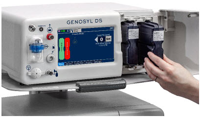
Insert the Cassette into the receptacle. Push in until you hear the Cassette click into the mechanism. 
The on-screen Cassette Status Indicator will switch to say "READY" and then prompt the user to begin a Water Trap/ Sample Line Leak Test. 2.13 Water Trap / Sample Line Leak Test
A Water Trap / Sample Line Leak Test is initiated when a Cassette has been inserted into the Console and fully seated, and if the measured NO is less than 1.0 ppm. Its purpose is to test the integrity of the Water Trap seal, the proper seating of the Water Trap, and the Sample Line connection to each Console, prior to operation. This is important to ensure an accurate measurement of NO within the ventilator circuit.
After the test has been initiated, the screen will prompt the Operator to close the Stopcock Valve and the Operator will have 60 seconds within which to do this. A numerical timer and a horizontal progress bar provide a visual representation of the time elapsed (red) and time remaining (gray). Once the Stopcock Valve has been closed and if the test has been successfully completed, the entire progress bar will turn green.
TEST IN PROCESS TEST PASSED 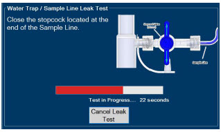
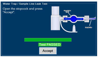
Figure 16: Water Trap / Sample Line Leak Test If the test has failed, the progress bar will remain red throughout the full 60 seconds. The Operator will be notified and prompted to troubleshoot the potential cause
Prior to completion of the leak test and if a condition exists in which immediate NO delivery is required, the Operator may cancel the leak test. The GENOSYL DS will allow a dose of 20 ppm to be set in Primary Dosing Mode. If a different dose is required, a Water Trap /Sample Line Leak Test must be completed.
The Water Trap / Sample Line Leak Test may also be initiated manually via the "Settings" tab and pressing the "Perform Leak Test" button. This may be useful to test the integrity of the Water Trap and Sample Line independent of the need to initiate the delivery of nitric oxide (see Settings in Section 2.8).
2.14 Console Shutdown - Cassette Status Indicator
The following describes the Cassette Status Indicators that will be shown on the display screen as the Console is shutting down. For proper Console shutdown procedures, see Section 6.
CASSETTE STATUS INDICATOR DESCRIPTION 
This Cassette Status Indicator will display "SAVE" on the shutdown screen to note which Cassette should be retained for future use. This Cassette has not been activated for dosing. 
This Cassette Status Indicator will display "DISPOSE" on the shutdown screen to note which Cassette should be disposed of per hospital policy.
This Cassette was used for dosing or has been activated.
This Cassette Status Indicator will appear on the shutdown screen to note no Cassette was inserted into the receptacle. 2.15 Battery Charge Status Indicator
CHARGE STATUS INDICATOR DESCRIPTION Solid Red Battery Power Supply Error.
See Battery Error Alarm in Section 10.3.Blinking Red Communication Failure or Hardware Error.
See Hardware Failure Alarm in Section 10.3.Solid Amber Console is unplugged and using battery power.
See System is running on low Battery Alarm in Section 10.5.Blinking Amber Console is using battery power and running on low battery.
See Low Battery Alarm in Section 10.5.Solid Green Console is plugged in and battery is fully charged. Blinking Green Console is plugged in and the battery is charging. GENOSYL ®DS
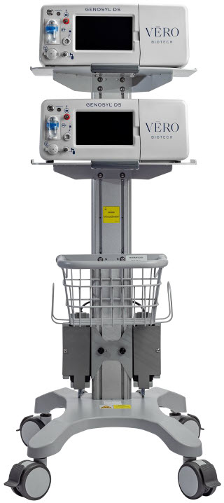
SECTION 3
SYSTEM SET-UP AND CONNECTIONS3. SYSTEM SET-UP AND CONNECTIONS
3.1 GENOSYL DS Set-Up and Mechanical Ventilator Circuit Schematic
NOTE Naming conventions: The GENOSYL DS accessories and components consist of the GENOSYL DS Injection Assembly with Adaptive Sensor, ( Section 3.4.1), or the GENOSYL DS Mixer Assembly with Adaptive Sensor ( Section 3.4.2), and the GENOSYL DS Gas Lines ( Section 3.5). Refer to Section 12.2 Table 15for when use of the Mixer Assembly with Adaptive Sensor is recommended. Connections and disposable circuits to breathing systems may vary and are unique to individual manufacturers. Example circuit diagrams are provided for reference. The schematic in Figure 17shows an example ventilator circuit set-up and connection to the GENOSYL DS, and a manual ventilation bagging system.
All required GENOSYL DS Parts / Components are listed in the front of this manual and should be removed from their packaging prior to set-up.
3.2 Connections to Various Breathing Systems
WARNING - ALWAYS use the GENOSYL DS in accordance with the indications, usage, contraindications, warnings, and precautions described in the GENOSYL prescribing information and labeling. Refer to latest approved prescribing information and labeling prior to use.
- The approved patient population for the GENOSYL DS as specified in the drug labeling for GENOSYL (nitric oxide) for inhalation, is limited to neonates. The GENOSYL DS is not intended to be used in other patient populations.
- ONLY use the GENOSYL DS, its parts, and accessories as instructed. Using non-specified components may result in product malfunction, injury or death.
- ALWAYS follow pre-use setup instructions for the routing and connections of tubing to avoid patient strangulation.
- MAKE SURE the System has all tubing connected as described in the instructions. Not connecting all tubing may result in inaccurate dosage and harm to the patient.
- DO NOT use accessories or cables other than those specified or provided by the manufacturer of this equipment, as this may result in increased electromagnetic emissions or decreased electromagnetic immunity of this equipment and result in improper operation.
CAUTION Prolonged use in dry environments without humidification will damage the gas sensors. Supplemental humidification providing greater than 20% relative humidity (RH) in the patient circuit is recommended. NOTE - All circuit components, including GENOSYL DS circuit components, should be changed out and disposed of according to hospital protocol.
- Refer to Section 8for use of the GENOSYL DS with an external transport ventilation device.
- Refer to Section 9for use of the GENOSYL DS with an anesthesia gas machine.
3.2.1 Conventional Ventilators
Compatibility testing has demonstrated performance meeting requirements for the GENOSYL DS operating range of 0 to 80 ppm with the following conventional ventilators at the operating ranges shown in Table 1.For further information on the use of the GENOSYL DS with validated MR conditional ventilators in the MR environment, refer to Section 7. For further information on the use of the GENOSYL DS with validated external transport ventilators, refer to Section 8. For use with validated anesthesia gas machine, see Section 9. See Section 12.2 Table 14for modes validated for each conventional ventilator. Validated ventilators were not tested with a nebulizer.
- Bio-Med Devices CrossVent 2+
- Bio-Med Devices MVP-10
- Dräger V500
- Dräger VN500
- Dräger V600
- Dräger VN600
- Dräger V800
- Dräger VN800
- Hamilton C1/T1
- Hamilton C6
- Hamilton G5
- Hamilton MR1
- Puritan Bennett 980
- Vyaire AVEA
WARNING - ALWAYS ensure the trigger sensitivity of the ventilator is checked after connecting the GENOSYL DS to the breathing circuit or when the dose is changed. The GENOSYL DS injects and samples gas from the patient respiratory circuit which may affect the triggering sensitivity of the ventilator.
- ALWAYS ensure the patient disconnect and high–pressure alarms are used with the ventilator.
- ONLY use the GENOSYL DS with Bio-Med Crossvent 2+ with Constant Flow ON. Not doing so may lead to elevated NO 2levels or dose variability.
CAUTION - When using spontaneousbreathing modes on respiratory device, NO 2levels may exceed 3.0 ppm when dosing ≥ 57 ppm NO into 100% FiO 2and maximum bias flow, resulting in nitric oxide delivery interruption. Once sample value of NO 2is below 3.0 ppm, the Console will auto resume delivery of NO at set dose. Refer to Section 12.1.5 Table 13for additional information.
- When using non-spontaneousbreathing modes on respiratory device, NO 2levels may exceed 3.0 ppm when dosing ≥ 63 ppm NO into 100% FiO 2and maximum bias flow, resulting in nitric oxide delivery interruption. Once sample value of NO 2is below 3.0 ppm, the Console will auto resume delivery of NO at set dose. Refer to Section 12.1.5 Table 13for additional information.
NOTE - If a higher than desired level of NO 2is measured in the patient circuit, increasing respiratory device bias flow, if applicable, may result in decreased NO 2levels.
Table 1: Conventional Ventilator Compatibility Test Ranges Setting Range Unit Inspiratory Flow Rate 2-120 LPM Respiratory Rate 6-60 BPM Peak Inspiratory Pressure 0-70 cmH 2O Positive End Expiratory Pressure 0-20 cmH 2O The ventilator circuit diagram for use withoutthe Inline Mixer accessory, required in certain scenarios, is shown in Figure 17. See Section 12.2, Table 15for applicable use scenarios.
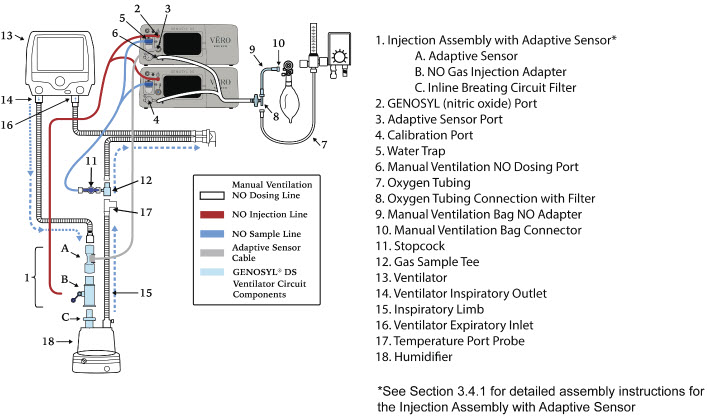
The ventilator circuit diagram for use withthe Inline Mixer accessory, required in certain scenarios, is shown in Figure 18. See Section 12.2, Table 15for applicable use scenarios.
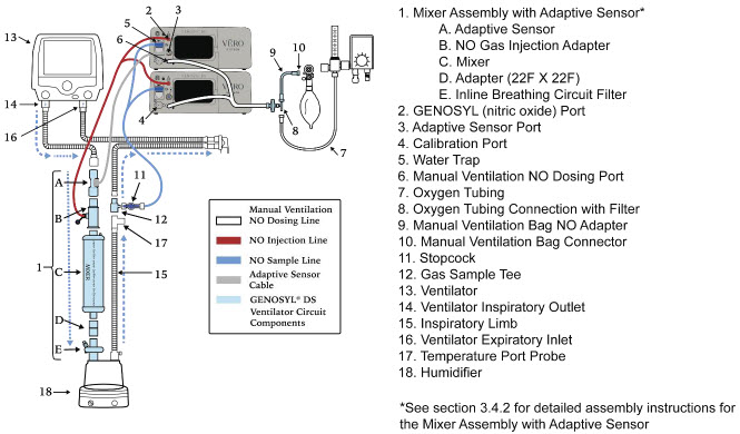
3.2.2 Non-Invasive Gas Delivery Systems
Compatibility testing has demonstrated performance meeting requirements for the GENOSYL DS operating range of 0 to 80 ppm with the following non-invasive gas delivery systems at operating ranges shown in Table 2.
- Fisher and Paykel Optiflow Jr 2 Breathing Circuit
- Fisher and Paykel Optiflow Breathing Circuit
Table 2: Non-Invasive Gas Delivery System Compatibility Test Ranges Setting Range Unit Optiflow Jr 2 Flow Rate 0.5 - 25 LPM Optiflow Flow Rate 5-60 LPM The Fisher and Paykel Optiflow Jr 2 Breathing Circuit for use with the GENOSYL DS is shown in Figure 19.
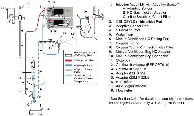
The Fisher and Paykel Optiflow Breathing Circuit for use with the GENOSYL DS is shown in Figure 20.
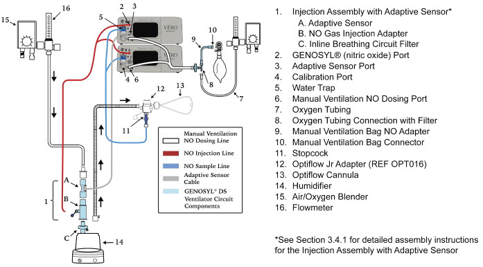
3.3 GENOSYL DS Ventilator Circuit Assembly Pre-Check
Follow the steps listed below for the initial System pre-check prior to completing the ventilator circuit assembly.
ILLUSTRATION ACTION Warnings, Cautions and Notes - Cassettes– 3 ea.
- Adaptive Sensor– 1 ea.
- Adaptive Sensor Cable– 1 ea.
- Gas Injection Adapter– 1 ea.
- Inline Breathing Circuit Filter1ea. (2 Inline Breathing Circuit Filters will be needed for use with an AGM. Refer to Section 9for more information about use with an AGM)
-
Mixer Assembly
- Mixer– 1 ea.
- Adapter(22mm ID × 22mm ID) – 1ea.
- Inline Breathing Circuit Filter– 1 ea.
- Gas Lines– 1 ea.
- Gas Sample Tee– 1 ea.
- Manual Ventilation Bag NO Adapter– 1 ea.
- Removeall items of the GENOSYL DS Parts / Components from packaging.
- Confirmthat the appropriate Cassettes for the intended use environment have been selected.
- Checkthe expiration date for each Cassette and the Inline Breathing Circuit Filterto ensure use is within the expiration date.
WARNING - DO NOT use a Cassette that is beyond its expiration date. Using an expired Cassette may affect the Cassette's ability to provide the correct NO dosage to the patient, which may cause injury or death.
- ONLY use External Transport Cassettes, identified by orange color and transport sticker, in external transport outside of the hospital.
NOTE A Mixer Assembly is not required for all use cases. Refer to Section 12.2, Table 15 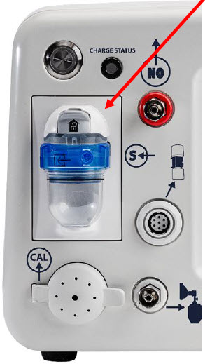
- Visually inspectthe Water Traps on both Consolesto ensure they are installed and empty.
WARNING ALWAYS empty Water Trap before each use, when prompted by the System, and when the trap is more than half full. Allowing the Water Trap to completely fill will occlude the Sample Line which will interrupt patient gas NO, NO 2, and O 2concentration monitoring. Failure to monitor the patient gas NO, NO 2, and O 2concentrations may result in patient injury.
ALWAYS conduct Water Trap / Sample Line Leak Test every time you empty and replace the Water Trap, as failure to do so may lead to an incorrect NO reading, which can result in injury or death.NOTE To empty the Water Trap, see Section 11.4.1. 3.4 Assembling GENOSYL DS Injection Assembly with Adaptive Sensor and GENOSYL DS Mixer Assembly with Adaptive Sensor
The Injection Assembly with Adaptive Sensor or the Mixer Assembly with Adaptive Sensor is the point of nitric oxide injection into the patient respiratory circuit. Only one type of assembly is required for each patient circuit. For certain scenarios, the Mixer Assembly with Adaptive Sensor is recommended to mix the NO gas with the gas supplied by the ventilator through a filter containing silica gel to provide intra-breath NO delivery. Refer to Section 12.2, Table 15for scenarios when a Mixer is recommended for use.
NOTE When using a Mixer, an Inline Breathing Circuit Filter must be used. If a Mixer is not used, an Inline Breathing Circuit Filter as presented in Figure 21may be used, or an Injection Line Filter connected to the port on the Gas Injection Adapter may be used. 3.4.1 GENOSYL DS Injection Assembly with Adaptive Sensor
Follow the instructions outlined below to assemble the GENOSYL DS Injection Assembly as shown in Figure 21.
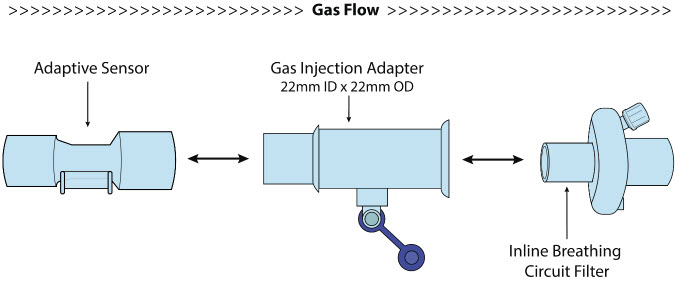
ILLUSTRATION ACTION 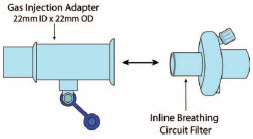
- Connectthe Inline Breathing Circuit Filter to the Gas Injection Adapter (22 mm ID × 22 mm OD).
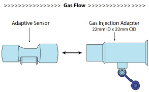
- Connectthe Adaptive Sensor to the inlet end of Gas Injection Adapter (22mm ID × 22 MM OD).
3.4.2 GENOSYL DS Mixer Assembly with Adaptive Sensor
If required, follow the instructions outlined below to assemble the GENOSYL DS Mixer Assembly with Adaptive Sensor as shown in Figure 22.
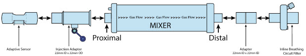
ILLUSTRATION ACTION 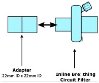
- Connectthe Inline Breathing Circuit Filter to the Adapter 22 mm ID × 22 mm ID.
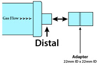
- Connectthe Adapter 22mm ID × 22 mm ID to the distal end of the Mixer.
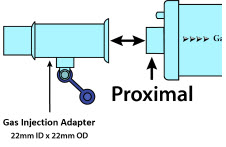
- Connectthe Gas Injection Adapter to the proximal end of the Mixer.
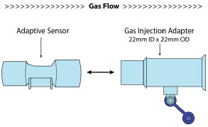
- Connectthe Adaptive Sensor to the proximal end of the Gas Injection Adaptor
3.5 GENOSYL DS Console Connections
3.5.1 GENOSYL DS Gas Line Connections
Follow the steps listed below to connect the GENOSYL DS Gas Lines to both Consoles.
ILLUSTRATION ACTION Warnings, Cautions and Notes 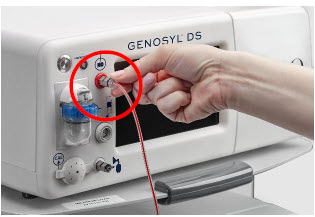
- Pushand twistclockwise the short Y-end of the NO Injection Line (red) to the "NO" port (red)on the front panel of the Dosing Console.
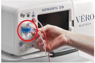
- Pushand twistthe short Y-end of the Sample Line (blue) to the Gas Sample Port (blue)on the front of the Water Trap, attached to the Dosing Console.
NOTE Ensure the Sample Lines are connected to the Water Traps on both Consoles. 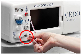
- Push and twist clockwise the end of the Manual Ventilation Line (clear) to the Manual Ventilation Port (clear)on the front panel of the Dosing Console
- Repeatsteps 1, 2, and 3 on the Back-up Console.
3.5.2 GENOSYL DS Sample Line Extension Connection
For use in the MR Environment, where a longer sample line is required follow the steps listed below to connect a Sample Line Extension. It is recommended to install the Sample Line Extension prior to initiation of dose.
ILLUSTRATION ACTION Warnings, Cautions and Notes 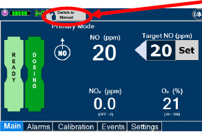
- If actively dosing, switchto Manual Dosing Mode prior to completing the following steps (see Section 5.4for details on Manual Dosing Mode).
WARNING Failure to switch to Manual Dosing Mode prior to installing a Sample Line Extension when the System is actively dosing may result in a spike in the NO dose delivered to the patient. 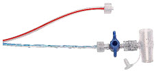
- Turnthe blue Stopcock Valve, attached at the Gas Sample Tee, to the closed position as shown.
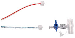
- Pushand twistcounterclockwise the Luer-Lock Collar of the Sample Line to remove from the blue Stopcock Valve at the Gas Sample Tee.
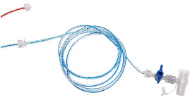
- Pushand twistclockwise the Luer-Lock Collar of the Sample Line onto the Sample Line Extension female connection.
- Pushand twistclockwise the Luer-Lock Collar of the Sample Line onto the blue Stopcock Valve at the Gas Sample Tee.
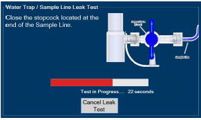
- PerformWater Trap / Sample Line Leak Test, as detailed in Section 2.13.
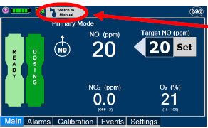
- If actively dosing, switchback to Primary Dosing Mode (see Section 5.4.2for details on resuming Primary dosing).
3.5.3 Sample Line Filter Connection
In cases when additional filtration of the sample line may be required (e.g.: Aerosol Delivery), follow the steps listed below to connect a Sample Line Filter.
ILLUSTRATION ACTION Warnings, Cautions and Notes 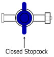
- Closethe blue stopcock to the position as shown
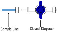
- Disconnectthe blue sample line from the blue stopcock, keeping the blue stopcock connected to the patient circuit.
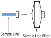
- Pushand twistcounterclockwise the Luer-Lock Collar of the Sample Line to remove from the blue Stopcock Valve at the Gas Sample Tee.
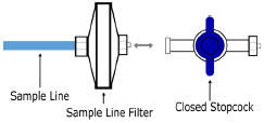
- Pushandtwistclockwise the male Luer-Lock Collar of the Sample Line Filter to the blue stopcock.
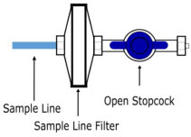
- Openthe blue stopcock valve to the position as shown.
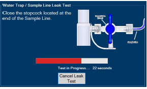
- PerformWater Trap / Sample Line Leak test, as detailed in Section 2.13.
3.5.4 GENOSYL DS Adaptive Sensor Cable Connection
Follow the step below to connect the Adaptive Sensor Cable to the Dosing Console.
ILLUSTRATION ACTION Warnings, Cautions and Notes 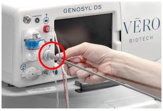
- Connectthe Adaptive Sensor Cable to the Adaptive Sensor Port on front of the Dosing Console.
NOTE The Adaptive Sensor should only be connected to the Dosing Console. 3.5.5 GENOSYL DS Respiratory Circuit Connections
Follow the steps listed below to connect the Gas Lines to the Injection Assembly, Sample Tee, and Adaptive Sensor. If a Sample Tee already exists within the ventilator circuit, the Sample Line may be connected directly to the existing Sample Tee.
ILLUSTRATION ACTION Warnings, Cautions and Notes 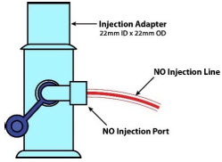
- Pushand twistclockwise the Luer-Lock Collar from the NO Injection Line onto the Injection Assembly.
NOTE After connecting, the valve assembly may have rotated such that the orientation may appear different from what is shown here and on the display screen. 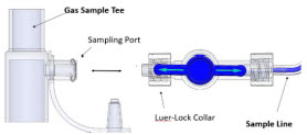
- Pushand twistclockwise the Luer-Lock Collar of the Sample Line onto the Sampling Port of the Gas Sample Tee.
NOTE Skip this step if a Gas Sample Tee is already connected and in-line with the ventilator circuit. 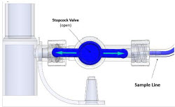
- Ensurethe blue Stopcock Valve is in the open position as shown.
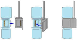
- Connectthe distal end of the Adaptive Sensor Cable to the Adaptive Sensor on the Injection Assembly
3.6 Manual Ventilation (Bag) Connection
Follow the steps listed below to connect the Manual Ventilation Line to a manual bagging system.
ILLUSTRATION ACTION 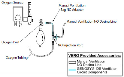
- Attachthe barbed end of the Manual Ventilation Bag NO Adapter into the oxygen tubing from the oxygen source.
- Attachthe other end of the NO Adapter to the oxygen port on the side of the Manual Ventilation Bag.
- Connectthe Manual Ventilation Line (clear) to the NO Injection Port of the Manual Ventilation Bag NO Adapter.
- Placethe Manual Ventilation Assembly in a clean accessible place if needed for future use.
3.7 Mechanical Ventilator Circuit Connections
Follow the steps outlined in this section to connect the GENOSYL DS Ventilator Circuit Assembly to the Mechanical Ventilator Circuit.
WARNING - ALWAYS ensure the trigger sensitivity of the ventilator is checked after connecting the GENOSYL DS to the breathing circuit or when the dose is changed. The GENOSYL DS injects and samples gas from the patient respiratory circuit which may affect the triggering sensitivity of the ventilator.
- ALWAYS ensure the patient disconnect and high–pressure alarms are used with the ventilator.
NOTE All ventilator connections should be assembled and inspected prior to connecting to the mechanical ventilator circuit. ILLUSTRATION ACTION Warnings, Cautions and Notes 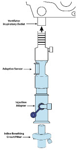
- Disconnectthe Inspiratory Tubing from the humidifier and attach it to the proximal end of the Injection Assembly to the Adaptive Sensor.
- Attachthe distal end of the Injection Assembly to the humidifier.
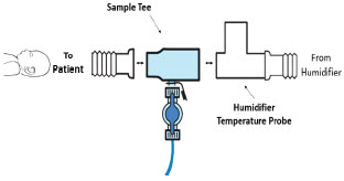
- Insertthe Sample Tee into the ventilator circuit at the proximal end of the temperature probe closest to the patient.
NOTE If a Gas Sample Tee is already connected and in-line with the ventilator circuit, connect the blue Sample Line directly to the existing Gas Sample Tee. 3.8 Gas Sampling During Aerosol Delivery
Follow the steps below to sample gas during Aerosol Delivery.
CAUTION Pneumatic Nebulizers will dilute the delivered nitric oxide dose. NOTE Replace filter after each treatment period. Change the filter if necessary due to Line Occlusion Alarm. ILLUSTRATION ACTION Warnings, Cautions and Notes 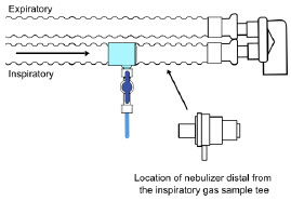
- Place the medication nebulizer downstream of the Gas Sample Tee on the inspiratory limb.
NOTE This placement avoids contamination of the sample system and prevents Line Occlusion Alarm from occurring. 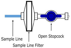
- Insert and Connectthe Sample Line Filter between the Sample Line and Blue Stopcock. (Refer to Section 3.5.3for detailed instructions)
GENOSYL ®DS
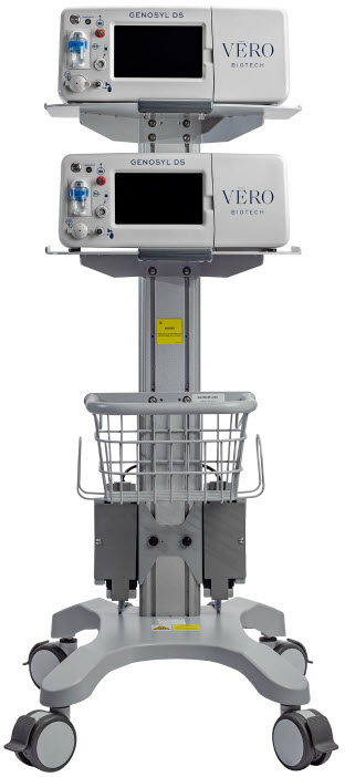
SECTION 4
SYSTEM START-UPFollow the instructions in this section to turn on both the Dosing and Back-up Consoles.
ILLUSTRATION ACTION Warnings, Cautions and Notes 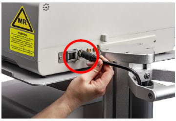
- Pushthe Circular Power Connectors into the back of the top and bottomConsoles.
- Connectthe main power cord to a grounded 120 V electrical outlet.
CAUTION ONLY use the GENOSYL DS with the power cord supplied by the manufacturer. Use of a generic power cord may cause output voltage instability leading to a touch screen failure.
ALWAYS ensure the power cord is firmly seated into the power supply and the wall outlet. A loose connection can result in damage to the device or faulty operation.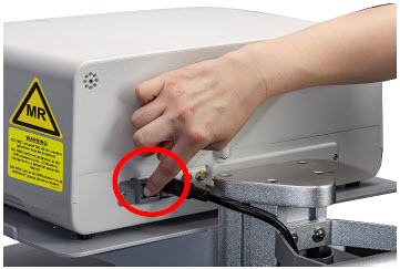
- Pressthe Black Rocker Power Switch, located on the back of eachConsole, to the right (ON position) to power on bothConsoles.
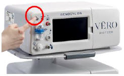
- Pressthe Silver Power Button, located at the top left corner on the front panel of eachConsole, to turn on the display screens on bothConsoles. The display screen will illuminate, and the Consoles will beep, indicating the power is on.
CAUTION The System will conduct an internal self-test. If an alarm or failure message should occur, refer to Section 10to resolve the issue. NOTE If the display screen does not turn on, see Troubleshooting, Section 10.8. 4.2 Cassette Insertion & Water Trap / Sample Line Leak Test
The following steps should be taken on both Consoles. Initiating Console Start-Up and inserting a Cassette for the Back-up Console at this stage will prepare it to serve as a Back-up for the Dosing Console.
Upon the insertion of a Cassette, a test will be initiated on each Console to check and ensure the integrity of the Water Traps and Sample Line (see Section 2.13). This helps ensure the accuracy of NO being delivered to the ventilator circuit.
The Water Trap / Sample Line Leak Test is automatically initiated upon one or both of the following conditions: 1) Insertion and seating of the Cassette if the measured NO is less than 1.0 ppm and/or 2) Insertion and seating of the Water Trap.
ILLUSTRATION ACTION Warnings, Cautions and Notes 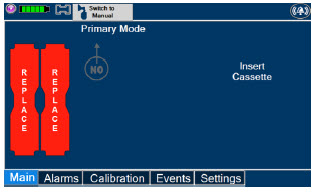
The following steps should be taken to insert the Cassettes into the Consoles. WARNING ALWAYS follow Cassette inspection instructions prior to insertion. Not inspecting the Cassette prior to insertion may lead to using a faulty Cassette, resulting in injury. NOTE Upon turning on the Consoles, the Cassette Indicator will display "Replace" 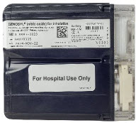
- Confirmthe Cassettes are blue.
WARNING Only use the orange External Transport Cassettes identified by orange color and transport sticker for use in external transport outside of the hospital. NOTE See Section 8for information about using the GENOSYL DS for external patient transfer outside of the hospital. 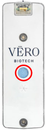
- Confirmthe Cassette State Window on eachCassette is blue.
WARNING DO NOT use the Cassette if the window is not blue. A Cassette State Window that is any color other than blue may affect the Cassette's ability to provide the correct NO dosage to the patient, which may cause injury or death. NOTE Cassette is inserted front first. The Cassette State Window is not visible when properly inserted. If the Cassette State Window is not blue, see Troubleshooting, Section 9.8 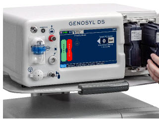
- Openthe Cassette Access Doors and inserttwo Cassettes into the Dosing Console and at least one Cassette into the Back-up Console. Push until it clicks.
NOTE Make sure Consoles are turned on before inserting the Cassette.
The Water Trap / Sample Line Leak Test is automatically initiated when the Cassette has been insertedand the measured NO is less than 1.0 ppm. After the first Cassette is fully inserted, the Operator will have 60 seconds to close the blue Stopcock Valveto perform the test ( Step 4below). Gas lines will need to be connected to the Console in order to pass the Water Trap / Sample Line Leak Test.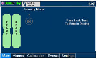
NOTE The Display Screen will temporarily indicate the Cassette has been detected, then automatically transition to the Water Trap / Sample Line Leak Test screen. 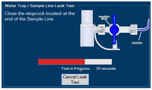
- Followthe onscreen instructions on both Consoles.
NOTE The screen will indicate the Water Trap / Sample Line Leak Test has started and the progress bar will be red until the Stopcock Valve has been closed, upon which it will then turn green if there is no leak detected.
Pressing "Cancel Leak Test", will allow for dosing in Manual Dosing Mode.
See Section 5.4for detail around dosing in Manual Dosing Mode.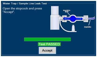
- Followthe onscreen instructions on both Consoles.
CAUTION Open the blue Stopcock Valve priorto pressing "Accept". Failure to do so will result in a line occlusion alarm. 4.2.1 Water Trap / Sample Line Leak Test Troubleshooting
NOTE If the Water Trap / Sample Line Leak Test fails, follow the onscreen instructions below to resolve the issue. Also see Troubleshooting, Section 10.8. ILLUSTRATION ACTION Warnings, Cautions and Notes 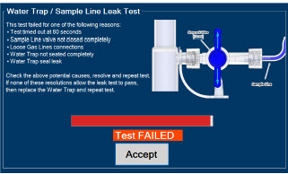
- If this screen is displayed, followthe onscreen instructions on both Consoles.
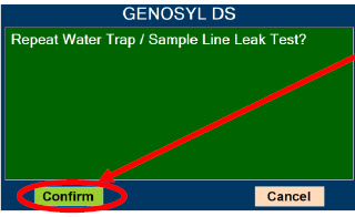
- Press"Confirm" on bothConsoles to begin a new Water Trap / Sample Line Leak Test.
NOTE NO Injection is held at 20 ppm until the completion of a successful Water Trap / Sample Line Leak Test. GENOSYL ®DS
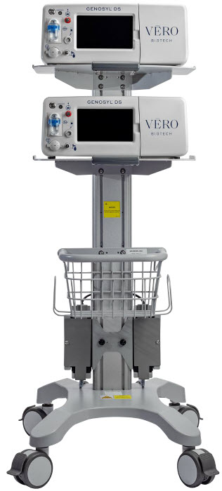
SECTION 5
NITRIC OXIDE ADMINISTRATION5. NITRIC OXIDE ADMINISTRATION
5.1 Nitric Oxide Dose Set-Up and Administration
The following steps are a continuation of Section 4.2, in which the Cassette will now be activated for nitric oxide administration.
WARNING - MAKE SURE the System stabilizes to the prescribed concentration (ppm) of NO prior to leaving the Console unattended. Failure to do so could result in under delivery of the target NO, leading to injury or harm.
- ALWAYS constantly monitor the patient. System malfunctions can occur if device and patient are not monitored and can result in injury or death. Careful monitoring is required by care personnel whenever the System is used on a patient. The use of an alarm and a monitoring system does not give an absolute assurance of warning for every malfunction that may occur. Certain alarms may require immediate response.
- If the gas flow of the patient's respiratory device/ventilator should be interrupted or discontinued, the NO dose should be maintained by switching to Manual Dosing Mode or the target NO dose should be set to zero.
5.1.1 Setting a Dose when using a Circuit withan Adaptive Sensor
This section describes how to set a nitric oxide dose when an Adaptive Sensor is used in the patient circuit. Refer to Section 3.2for recommended set up diagrams.
ILLUSTRATION ACTION Warnings, Cautions and Notes 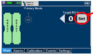
- Pressthe gray "Set" button on the display screen.
Note The Adaptive Sensor must detect flow through the breathing circuit to set a dose. 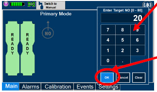
- Enterthe prescribed dose in ppm on the electronic keypad.
- PressOK to confirm the entry.
NOTE The time to reach target dose may vary up to 10 minutes. If unable to set the dose in Primary Dosing Mode, see Troubleshooting, Section 10.8. NOTE If manual ventilation is required, proceed to Section 5.4.
When adjusting dose, proceed to Section 5.2.
If dosing is completed, proceed to Section 6.1.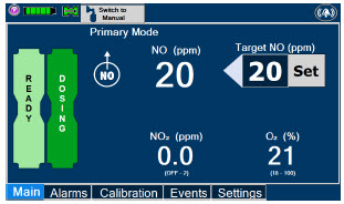
NOTE The display screen will look as shown after completing steps 1-3. NOTE The NO 2sensor reading may appear as "—" for the first 30 seconds of dosing while the sample System is preparing. 5.1.2 Setting a Dose when using a Circuit withoutan Adaptive Sensor
This section describes how to set a nitric oxide dose when an Adaptive Sensor is not used in the patient circuit, such as when initiating a dose when using a Console as Backup ( Section 5.5). Refer to Section 3.2for recommended set up diagrams. In the absence of an Adaptive Sensor, the GENOSYL DS will properly deliver and control nitric oxide dose. However, the user will have to manually select a Total Flow range.
ILLUSTRATION ACTION Warnings, Cautions and Notes 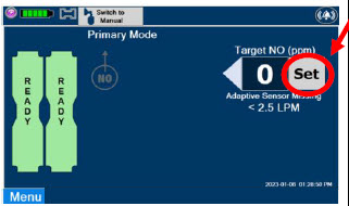
- Pressthe gray "Set" button on the display screen.
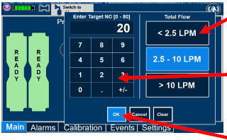
- ConfirmTotal Flow range is appropriately selected.
- Enterthe prescribed dose in ppm on the electronic keypad.
- PressOK to confirm the entry.
NOTE The time to reach target dose may vary up to 10 minutes.
If unable to set the dose in Primary Dosing Mode, see Troubleshooting, Section 10.8.NOTE If manual ventilation is required, proceed to Section 5.4.
When adjusting dose, proceed to Section 5.2.
If dosing is completed, proceed to Section 6.1.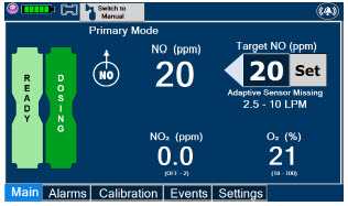
NOTE The display screen will look as shown after completing steps 1-3. NOTE The NO 2sensor reading may appear as "--" for the first 30 seconds of dosing while the sample system is preparing. To adjust the dose of nitric oxide administered per hospital protocol or physician order, follow the instructions listed below.
5.2.1 Adjusting the Dose when using a Circuitwithan Adaptive Sensor
ILLUSTRATION ACTION Warnings, Cautions and Notes 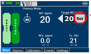
- Pressthe gray "Set" button to access the electronic keypad on the display screen on the Dosing Console.
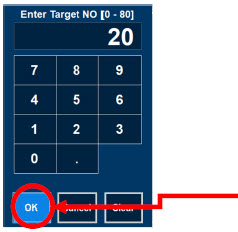
- Enterthe prescribed dose using the electronic keypad.
- Press"OK" to confirm the dose and to start dosing administration.
NOTE If dosing is complete, proceed to Section 6. 5.2.2 Adjust the Dose and Flow Range when using a Circuitwithoutan Adaptive Sensor
ILLUSTRATION ACTION Warnings, Cautions and Notes 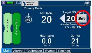
- Pressthe gray "Set" button to access the electronic keypad on the display screen on the Dosing Console.
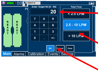
- Enterthe prescribed ppm dose using the numeric keypad.
- Adjust Total Flow range, if necessary.
- Press"OK" to confirm the dose and to start dosing administration.
NOTE If dosing is complete, proceed to Section 6. 5.3 Replacement of a Depleted Cassette
The GENOSYL DS automatically switches from the dosing Cassette to the secondary Cassette in the Dosing Console once the Cassette is depleted if a secondary Cassette is properly inserted and preheated. After transition, the depleted Cassette is automatically ejected.
CAUTION User should always have a secondary Cassette inserted in the Dosing Console and preheated in order for auto transition to occur. User should replace depleted Cassette as soon as possible after ejection. ILLUSTRATION ACTION Warnings, Cautions and Notes 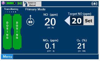
NOTE The Console will automatically transition to the secondary Cassette if properly inserted and preheated. The screen to the left will be displayed during the transition process. 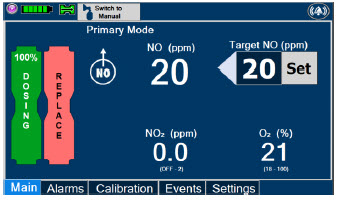
- Follow onscreen instructions to replace Cassette.
NOTE - When entering Manual Dosing Mode, the set target dose in Primary Dosing Mode will carry over to Manual Dosing Mode if 5 ppm or greater. Less than 5 ppm set target dose in Primary Dosing Mode will default to 5 ppm dose in Manual Dosing Mode. However, dose and flow rate may need to be adjusted for specific situations. The GENOSYL DS Smart Feedback System™ is disabled while in Manual Dosing Mode. To reinitiate the Smart Feedback System, switch back to Primary Dosing Mode as soon as the situation permits.
- After a Console is in Manual Dosing Mode for more than two minutes, a reminder tone will sound in ten second intervals to alert the user that the Console is still in Manual Dosing Mode.
5.4.1 Manual Ventilation Use (Bagging)
This section will describe NO administration when manual ventilation is required.
WARNING - ALWAYS ensure that the manual flow displayed on the Console matches the flow set into the resuscitation bag. Incorrect flow settings may result in an incorrect estimation of NO delivery. If the flow into the manual equipment is too low, there is risk of overdosing the patient with NO.
- ALWAYS squeeze the bag several times, after starting fresh gas flow, to empty residual gas in the bag prior to using the System to ventilate a patient. Failure to do so could result in higher NO 2levels being delivered to the patient.
- ALWAYS use the smallest bag adequate to deliver the desired tidal volume. Failure to do so could result in higher NO 2levels being delivered to the patient.
- ONLY use a manual resuscitation bag with the GENOSYL DS for a short time (e.g., less than one hour) when on battery only. Otherwise, the System may shut off and may result in injury or death.
ILLUSTRATION ACTION Warnings, Cautions and Notes 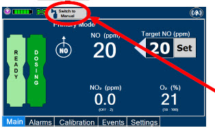
- Ensurethe oxygen flow source is set appropriately or adjust as needed.
- Pressthe button "Switch to Manual" on the Dosing Console.
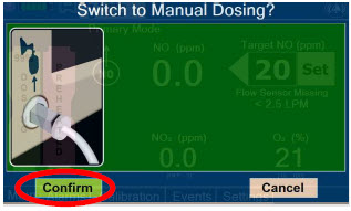
- Press "Confirm" to switch to Manual Dosing.
WARNING If the dilution flow rate displayed on the screen does not match the wall source, then the estimated NO may be inaccurate. 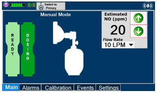
NOTE Dosing has been initiated at the same dose (ppm) as set in Primary Dosing Mode.
If the primary dosing was set at "0" prior to pressing the "Switch to Manual" button, the estimated NO will also be at "0" and will need to be adjusted.
If the dose was set between 1 and 5 ppm prior to pressing the "Switch to Manual" button, the estimated NO dose will also be at"5 ppm" and may be adjusted.
In the event dose is initiated in Manual Dosing Mode, the console will default to 20 ppm, which can be adjusted as needed.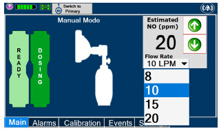
- To resumeprimary dosing, see Section 5.4.3.
NOTE If an adjustment of the NO concentration is required, press the green up and down arrows.
If an adjustment to the Dilution Flow Rate is required while in Manual Dosing Mode, press the LPM value and a dropdown menu will expand. Press the prescribed value. The new value will be highlighted in blue and the dropdown menu will collapse.5.4.2 Preset Manual Dosing Mode Flow Rate (OPTIONAL)
User has the option to preset a Manual Dosing Mode Flow rate. This can be completed during set up or at any time.
ILLUSTRATION ACTION Warnings, Cautions and Notes 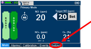
- Navigate to the "Settings" Tab.
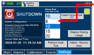
- Selectthe Flow Rate from the drop-down menu.
NOTE The Console will default to a Flow Rate of 10 LPM if not adjusted.
Any adjustment will be retained until the Console is powered down.This section describes the process for resuming primary dosing from Manual Mode.
ILLUSTRATION ACTION Warnings, Cautions and Notes 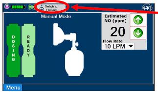
- Pressthe "Switch to Primary" button at the top of the Manual Mode screen.
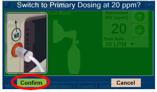
- Press"Confirm" to start dosing or "Cancel" to cancel.
NOTE The NO dose used in Manual Mode will become the set target dose in Primary Mode. 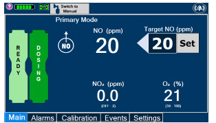
NOTE The display screen will look as shown after completing steps 1-2. This section describes the process of activating the Cassette in the Back-up Console. Delivery of NO will begin immediately upon Cassette activation.
DISPLAY ACTION Warnings, Cautions and Notes 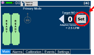
- Press the "Set" button on the Back-up Console which will display the NO dose electronic keypad and Flow Selection menu.
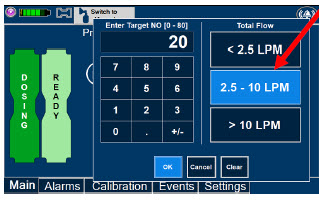
- Confirm Dose and Total Flow range is appropriately selected.
- Press "OK" to confirm entry
NOTE The Back-up Console screen will be as shown.
The default Total Flow range displayed will be <2.5LPM and the default dose will be 20 ppm unless otherwise selected by the user. See Section 5.1.2
The Back-up Console is now the Dosing Console.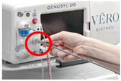
- Connect the Adaptive Sensor Cable to the front of the new Dosing Console.
GENOSYL ®DS
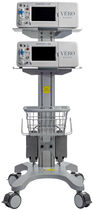
SECTION 6
CONSOLE SHUTDOWN6. CONSOLE SHUTDOWN AND CASSETTE DISPOSAL
WARNING NEVER turn the rear power switch OFF until the System has gone through a controlled shutdown or instructed by VERO Technical Support. Turning the rear power switch OFF prematurely (e.g., while it is still in use) will immediately shut down the device. This may result in interruption in NO delivery to the patient, which may cause injury or death. CAUTION NEVER turn the rear power switch OFF until the System has gone through a controlled shutdown or instructed by VERO Technical Support. Turning the rear power switch OFF prematurely (e.g., while it is still in use) will immediately shut down the device and may cause improper operation upon restart. NOTE It is recommended that the Console be rebooted at least once every 30 days. If the administration of NO must be stopped, then the dose level must be set to "0". The following procedure describes how to remove the Cassette and the following section will describe how to shut down the Console.
DISPLAY ACTION Warnings, Cautions and Notes 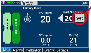
- Pressthe gray "Set" button to access the electronic keypad on the display screen.
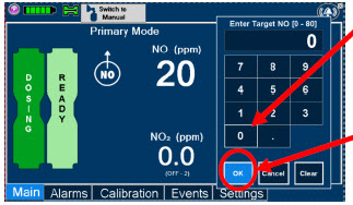
- Setthe dose to "0" using the electronic keypad.
- Press"OK" to confirm the entry.
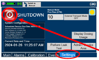
- If the "Settings" tab is not displayed, pressthe "Menu" tab to access the sub-level tabs.
- Pressthe "Settings" tab on the display menu.
- Pressthe red "System Shutdown" icon.
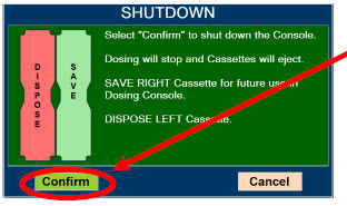
- Reviewon screen prompt.
- Press"Confirm" to confirm shutdown.
- Waituntil the Console shuts down, the display screen appears blank, and the Console emits an audible beep.
NOTE If the System does not shut down, see Troubleshooting , Section 10.8.
The screen will inform user if Cassette should be saved or disposed of. Refer to Section 2.14Shutdown Cassette Status Indicator description.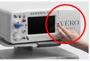
- Openthe Cassette Access Door.
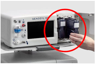
- Removethe Cassettes by pulling the Cassette straight out.
- Disposethe inerted Cassettes per hospital policy.
NOTE The Console will inert any remain contents from a dosing Cassette upon ejection, rendering it unusable. If a Cassette has only been preheated, and not used for dosing, the contents have not been inerted and it can still be used. The Cassette State Window will remain blue on Cassettes that have not been inerted. 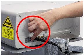
- Pressthe Black Rocker Power Switch to the "OFF" position.
- Repeatsteps 1-13 for the other Console.
WARNING NEVER turn the rear power switch OFF until the System has gone through a controlled shutdown or instructed by VERO Technical Support. Turning the rear power switch OFF prematurely (e.g., while it is still in use) will immediately shut down the device. This may result in interruption in NO delivery to the patient, which may cause injury or death. CAUTION NEVER turn the rear power switch OFF until the System has gone through a controlled shutdown or instructed by VERO Technical Support. Turning the rear power switch OFF prematurely (e.g., while it is still in use) will immediately shut down the device and may cause improper operation upon restart. Following dosing use, any remaining Cassette liquid contents in a dosing Cassette are purged into an inerting chamber that is built into the Cassette, where the contents are chemically neutralized, rendering the Cassette safe for disposal. When the Cassette liquid contents are emptied into the inerting chamber, the Cassette State Window on the front of the Cassette reddens and bleaches from its original blue color, indicating the Cassette is depleted. The Cassette can now be disposed of per hospital policy.
GENOSYL ®DS
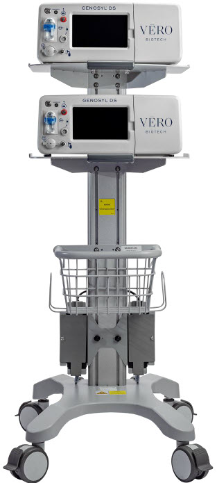
SECTION 7
USING THE SYSTEM IN THE MR SCANNER ROOM7. USING THE SYSTEM IN THE MR SCANNER ROOM
WARNING - The GENOSYL DS is classified as MR Conditional with MR scanners of 1.5 or 3.0 Tesla strength ONLY in areas where the field strength is less than 100 gauss.
- ALWAYS operate at a fringe field of less than 100 gauss. This device contains ferromagnetic components and may experience strong attraction close to the magnet.
- DO NOT exceed 100 gauss; System operation may be impacted. Confirm Cart caster lock function. Optionally connect tether.
- NEVER use the GENOSYL DS in the MR scanner room without gauss alarms installed.
- ALWAYS verify at least one gauss alarm is functioning properly prior to use in the MR environment.
- DO NOT use the GENOSYL DS in the MR environment if neither gauss alarm is functional.
- ALWAYS move System away from the MR scanner if the gauss alarm sounds. The gauss alarm will sound if the System is too close to the MR scanner. Move System away from the MR scanner until the gauss alarm stops sounding.
- ALWAYS verify that the GENOSYL DS Cart casters are locked after positioning the System in the MR scanner room.
- ALWAYS verify that the GENOSYL DS is securely attached to the Cart.
- ALWAYS arrange power cord, MR patient gas sample line, and NO delivery line to avoid entanglement, strangulation and/or a trip hazard.
- DO NOT use the GENOSYL DS in the MR environment if the Cart moves when the brake caster locks are engaged.
- NEVER perform NO or NO 2calibration within the MR scanner room. Calibration equipment is a potential projectile hazard.
NOTE Refer to Section 13.11for MR Signal-to-Noise Ratio and Artifact Dimension Analysis 7.1 Connection to the Ventilator Breathing Circuit
To connect the GENOSYL DS to an MR Conditional ventilator, see Section 3.2for example breathing circuits. When using the GENOSYL DS in the MR environment, a Sample Line Extension may be required. See Section 3.5.2for steps to install the Sample Line Extension.
NOTE - Connections to various ventilators are unique to each manufacturer as well as their corresponding disposable circuits.
- A Sample Line Extension may be required. Refer to Section 3.5.2for instructions to install a Sample Line Extension.
7.2 Transferring to and from the MR Scanner Room
WARNING - NEVER use the GENOSYL DS in the MR scanner room without gauss alarms installed.
- DO NOT use the GENOSYL DS in the MR environment if neither gauss alarm is functional.
- ALWAYS verify at least one gauss alarm is functioning properly prior to use in the MR environment.
- ALWAYS verify that the GENOSYL DS is securely attached to the Cart.
- NEVER perform NO or NO 2calibration within the MR scanner room. Calibration equipment is a potential projectile hazard.
1. Verifythat both gauss alarms are installed on the GENOSYL DS Cart.
2. Movethe patient, MR conditional ventilator circuit, and GENOSYL DS into the MR scanner room.
3. Positionthe GENOSYL DS outside of the MR exclusion zone, as shown in Figure 23.
WARNING ALWAYS move System away from the MR scanner if the gauss alarm sounds. The gauss alarm will sound if the System is too close to the MR scanner. Move System away from the MR scanner until the gauss alarm stops sounding. 4. Engagethe locks on wheels and confirm caster lock function. Attaching a facility supplied tether to the System Cart handle may be utilized as a redundant means to limit the distance the Cart can move.
WARNING - ALWAYS verify that the GENOSYL DS Cart casters are locked after positioning the System in the MR scanner room.
- DO NOT use the GENOSYL DS in the MR environment if the Cart moves when the brake caster locks are engaged.
5. Movethe patient, MR conditional ventilator, and GENOSYL DS outside of the MR scanner room.
6. Verifyventilator and GENOSYL DS function following transition from the MR scanner room.
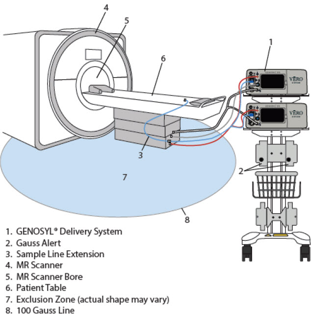
GENOSYL ®DS
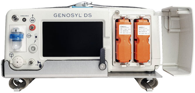
SECTION 8
EXTERNAL TRANSPORTWARNING - ALWAYS use the GENOSYL DS in accordance with the indications, usage, contraindications, warnings, and precautions described in the GENOSYL prescribing information and labeling. Refer to latest approved prescribing information and labeling prior to use.
- The approved patient population for the GENOSYL DS as specified in the drug labeling for GENOSYL (nitric oxide) for inhalation, is limited to neonates. The GENOSYL DS is not intended to be used in other patient populations.
- ALWAYS ensure the GENOSYL DS Dosing and Back-up Consoles are securely affixed to the External Transport Mounts when the System used in a transport vehicle.
- ALWAYS ensure Consoles are placed into External Transport Mode before inserting a Cassette for external transport outside of the hospital.
- ALWAYS have a second Console present and properly connected when a Dosing Console is connected to the patient. If the Dosing Console malfunctions, switch to the Back-up Console. If the Back-up Console is not available or properly connected, this may result in patient injury or death.
- ONLY use External Transport Cassettes, identified by orange color and transport sticker, in external transport outside of the hospital.
- ALWAYS ensure the External Transport Mounts are secured during patient transport, per hospital protocols.
CAUTION Prolonged use in dry environments without humidification will damage the gas sensors. Supplemental humidification providing greater than 20% relative humidity (RH) in the patient circuit is recommended. 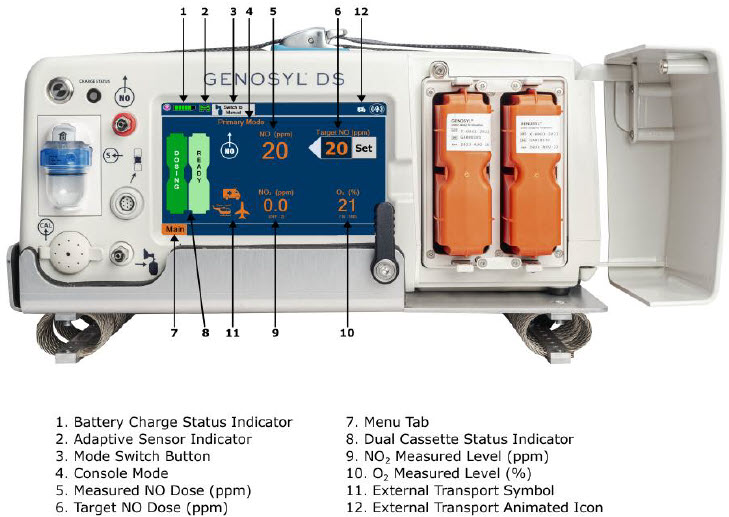
Compatibility testing has demonstrated performance meeting requirements for the GENOSYL DS operating range of 0 to 80 ppm with the following external transport ventilation devices at the operating ranges shown in Table 3, including Manual Ventilation mode, while External Transport Mode is turned ON and while using an External Transport Cassette.
- Hamilton T1
- International Bio-Med Crossvent 2+
- International Bio-Med MVP-10
WARNING - The GENOSYL DS injects and samples gas from the patient respiratory circuit which may affect the triggering sensitivity of the ventilator. ALWAYS ensure the trigger sensitivity of the ventilator is checked after connecting the GENOSYL DS to the breathing circuit or when the dose is changed, and adjust trigger sensitivity as necessary. Failure to do so may lead to ventilator auto cycling or apnea alarm.
- ALWAYS ensure the patient disconnect and high–pressure alarms are used with the ventilator.
- ONLY use the GENOSYL DS with Bio-Med Crossvent 2+ with Constant Flow ON. Not doing so may lead to elevated NO 2levels or dose variability.
CAUTION - When using spontaneousbreathing modes on respiratory device, NO 2levels may exceed 3.0 ppm when dosing ≥ 57 ppm NO into 100% FiO 2and maximum bias flow resulting in nitric oxide delivery interruption. Once sample value of NO 2is below 3.0 ppm, the Console will auto resume delivery of NO at set dose. Refer to Section 12.1.5 Table 13for additional information.
- When using non-spontaneousbreathing modes on respiratory device, NO 2levels may exceed 3.0 ppm when dosing ≥ 63 ppm NO or greater into 100% FiO 2and maximum bias flow resulting in nitric oxide delivery interruption. Once sample value of NO 2is below 3.0 ppm, the Console will auto resume delivery of NO at set dose. Refer to Section 12.1.5 Table 13for additional information.
Table 3: External Transport Ventilation Devices Compatibility Testing Ranges Setting Range Unit Inspiratory Flow Rate 2-120 LPM Respiratory Rate 6-60 BPM Peak Inspiratory Pressure 0-70 cmH 2O Positive End Expiratory Pressure 0-20 cmH 2O For use in patient external transport, the Dosing and Back-up Consoles must be securely mounted within the transport vehicle per hospital transport protocols. Figure 25illustrates the GENOSYL DS in an External Transport Mount.
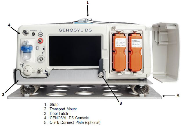
Prior to using the GENOSYL DS in external transport, both Consoles must have External Transport Mode ON with two External Transport Cassettes in the Dosing Console and at least one External Transport Cassette inserted into the Back-up Console. See Figure 26for a diagram of the External Transport Cassette and Section 8.2.1for instructions to turning External Transport Mode ON.
External Transport Cassette in packaging
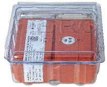
Unused External Transport Cassette

Inerted External Transport Cassette

Figure 26: External Transport Cassette Example circuit diagrams for connection of the GENOSYL DS to a transport ventilator are shown in Figure 27(International Bio-Med Circuit) and Figures 28and 29for other conventional ventilators.
Additional disposable items recommended for external transport may include:
- GENOSYL External Transport Cassettes
- GENOSYL DS Gas Lines
- Water Trap
- GENOSYL DS Manual Bag NO Adapter
- Components for connection to breathing circuit
External transport equipment weight should be calculated to ensure transport system meets weight allowance.
Table 4: External Transport Equipment Specifications Part Description Weight per Unit Dimensions Number Required Total Weight Console 8.85 kg
(19.75 lb)40.6 cm × 34.29 cm × 17 cm
(16 in × 13.5 in × 6.75 in)2 17.7 kg
(39.5 lb)External Transport Cassette 0.42 kg
(0.93 lb)11.4 cm × 3.8 cm × 13 cm
(4.5 in × 1.5 in × 5.1in)3 1.26 kg
(2.79 lb)External Transport Mount 2.22 kg
(4.89lb)40.64 cm × 32.77 cm × 8.89 cm
(16 in × 12.9 in × 3.5 in)2 4.44 kg
(9.78 lb)Quick Connect Plate 1.52 kg
(3.35 lb)46.36 cm × 27.18 cm × 0.64 cm
(18.25 in × 10.70 in × 0.25 in)(1 Optional) 1.52 kg
(3.35 lb)Power Supply 2.07 kg
(4.56 lb)14.6 ft 1 2.07 kg
(4.56 lb)Note: All sizes and weights are approximate and may vary slightly.
8.1 External Transport Set-Up and Ventilator Circuit Schematics
8.1.1 Securing a Console in a Transport Mount
GENOSYL DS Consoles must be secured into the External Transport Mount before used in external transport.
ILLUSTRATION ACTION WARNINGS, CAUTIONS, AND NOTES 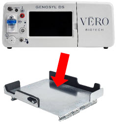
- Confirman External Transport Mount is secured to the external transport sled.
- Placethe Console into the External Transport Mount.
WARNING ALWAYS ensure the External Transport Mounts are secured during patient transport, per hospital protocols.
ALWAYS ensure the GENOSYL DS Dosing and Back-up Consoles are securely affixed to the External Transport Mounts when the System will be used in an external transport vehicle.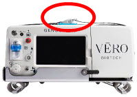
- Pullthe strap on top of the Console securely tight to cinch into place.
- Repeatsteps 1-3 for the other Console.
NOTE Connections to various ventilators as well as their corresponding disposable circuits are unique to each manufacturer. 8.1.2 Connection to an International Bio-Med External Transport Ventilator Circuit
An example circuit diagram for connection of the GENOSYL DS to a dual-limb external transport ventilator is shown in Figure 27.The dual-limb circuit is used for ventilators such as the International Bio-Med Crossvent 2+ and International Bio-Med MVP-10.
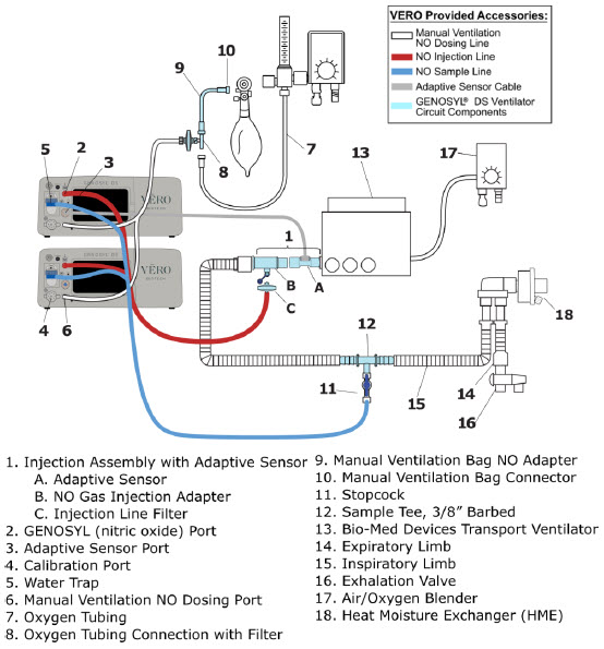
Follow the steps outlined below to connect the GENOSYL DS to a Dual-Limb External Transport Ventilator Circuit for ventilators such as the International Bio-Med Crossvent 2+ and International Bio-Med MVP-10.
ILLUSTRATION ACTION 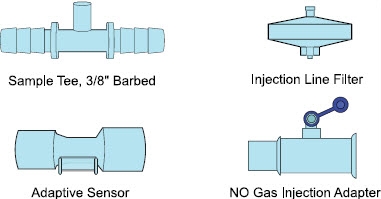
- Obtainone (1) Sample Tee, 3/8" Barbed, one (1) GENOSYL DS Adaptive Sensor, one (1) NO Gas Injection Adapter, and one (1) Injection Line Filter.
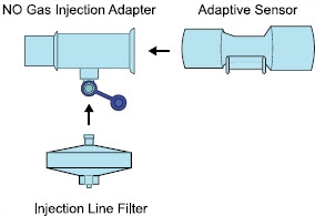
- Connectthe GENOSYL DS Adaptive Sensor, NO Gas Injection Adapter, and the Injection Line Filter to create the Gas Injection Assembly.
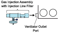
- Connectthe GENOSYL DS Adaptive Sensor of the Gas Injection Assembly with Injection Line Filter to the ventilator outlet port.
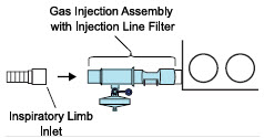
- Connectthe inspiratory limb inlet to the NO Gas Injection Adapter of the Gas Injection Assembly with Injection Line Filter.
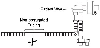
- Locate and cutthe noncorrugated tubing at the center of the smooth segment closest to the patient wye.
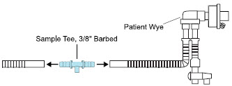
- Insertthe barbed ends of the Sample Tee, 3/8" Barbed into both ends of the cut tubing.
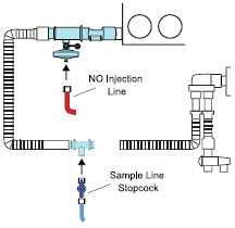
- Pushand twistclockwise the Luer-Lock Collar from the NO Injection Line onto the Injection Assembly with Injection Line Filter.
- Pushand twistclockwise the Luer-Lock Collar of the Sample Line Stopcock onto the Sampling Port of the Sample Tee, 3/8" Barbed.
Instructions for connecting gas lines to GENOSYL DS Consoles can be found in Section 3.5.1. Section 3.5.4covers connecting an Adaptive Sensor Cable to Dosing Console, and Section 3.5.5details connecting it to the Adaptive Sensor on the Injection Assembly.
8.1.3 Connection to a Conventional External Transport Ventilator
An example circuit diagram for connection of the GENOSYL DS to an external transport ventilator when using an Injection Assembly with Adaptive Sensor is shown in Figure 28and when using a Mixer Assembly with Adaptive Sensor is shown in Figure 29with transport ventilators such as the Hamilton T1. See Section 12.2 Table 15for applicable use scenarios.
8.1.3.1 Connection to a Conventional External Transport Ventilator using an Injection Assembly with Adaptive Sensor
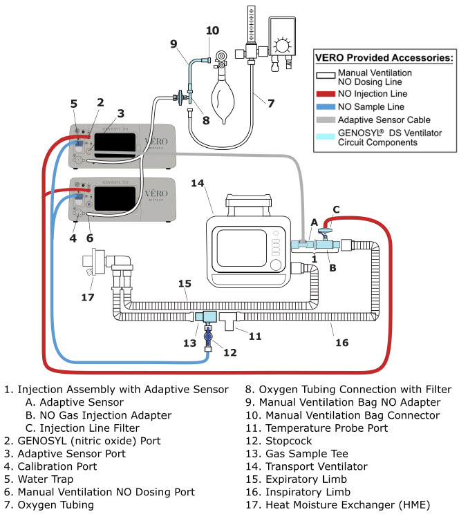
Follow the instructions outlined below to assemble the GENOSYL DS Injection Assembly with Adaptive Sensor.
ILLUSTRATION ACTION 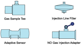
- Obtainone (1) Gas Sample Tee, one (1) GENOSYL DS Adaptive Sensor, one (1) NO Gas Injection Adapter, and one (1) Injection Line Filter.
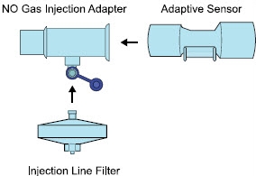
- ConnectGENOSYL DS Adaptive Sensor, NO Gas Injection Adapter, and the Injection Line Filter to create the Gas Injection Assembly.
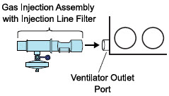
- Connectthe GENOSYL DS Adaptive Sensor of the Gas Injection Assembly with Injection Line Filter to the ventilator outlet port.

- Connectthe inspiratory limb inlet to the NO Gas Injection Adapter of the Gas Injection Assembly with Injection Line Filter.
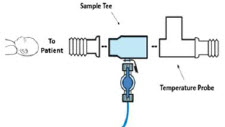
- Insertthe Sample Tee into the ventilator circuit at the proximal end of the temperature probe closest to the patient.
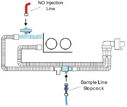
- Pushand twistclockwise the Luer-Lock Collar from the NO Injection Line onto the Injection Assembly with Injection Line Filter.
- Pushand twistclockwise the Luer-Lock Collar of the Sample Line Stopcock onto the Sampling Port of the Sample Tee, 3/8" Barbed.
Instructions for connecting gas lines to GENOSYL DS Consoles can be found in Section 3.5.1. Section 3.5.4covers connecting an Adaptive Sensor Cable to Dosing Console, and Section 3.5.5details connecting it to the Adaptive Sensor on the Injection Assembly.
8.1.3.2 Transport Ventilator Circuit Set-Up and Connections using Mixer Assembly with Adaptive Sensor
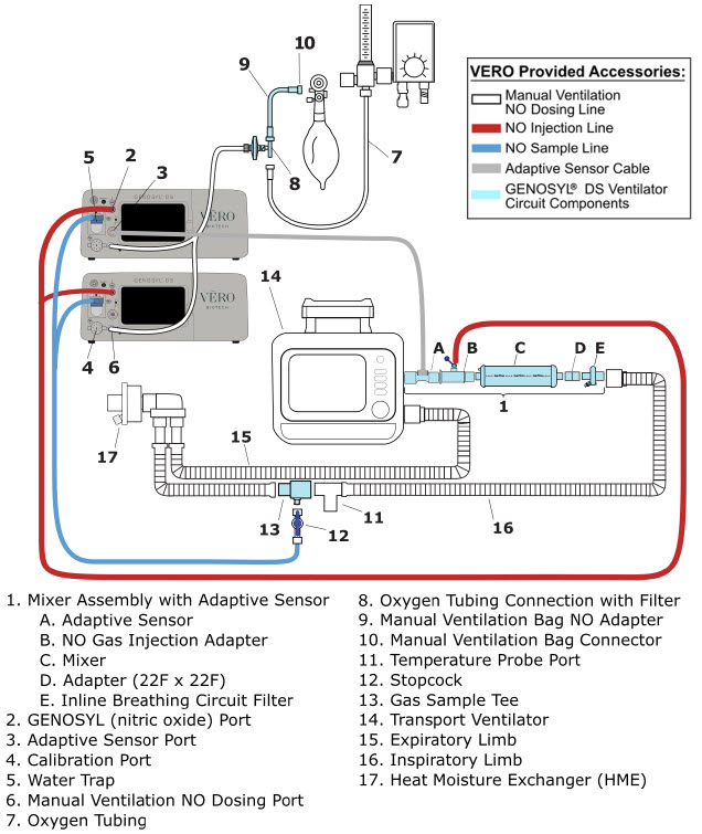
Follow the instructions outlined below to assemble the GENOSYL DS Mixer Assembly with Adaptive Sensor.
ILLUSTRATION ACTION 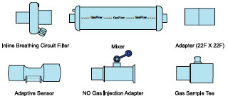
- Obtainone (1) Inline Breathing Circuit Filter, (1) Mixer, (1) Adapter, (1) Adaptive Sensor (1), NO Gas Injection Adapter, and (1) Gas Sample Tee.
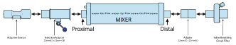
- Connectthe GENOSYL DS Adaptive Sensor, NO Gas Injection Adapter, Mixer, Adapter and the Inline Breathing Circuit Filter to create the Mixer Assembly.
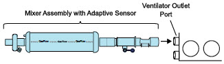
- Connectthe GENOSYL DS Adaptive Sensor of the Mixer Assembly to the ventilator outlet port.
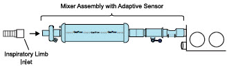
- Connectthe inspiratory limb inlet to the NO Gas Injection Adapter of the Mixer Assembly with Adaptive Sensor.
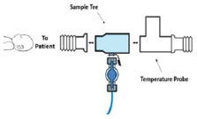
- Insertthe Sample Tee into the ventilator circuit at the proximal end of the temperature probe closest to the patient.
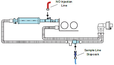
- Pushand twistclockwise the Luer-Lock Collar from the NO Injection Line onto the Injection Assembly with Injection Line Filter.
- Pushand twistclockwise the Luer-Lock Collar of the Sample Line Stopcock onto the Sampling Port of the Sample Tee, 3/8" Barbed.
Instructions for connecting gas lines to GENOSYL DS Consoles can be found in Section 3.5.1. Section 3.5.4covers connecting an Adaptive Sensor Cable to Dosing Console, and Section 3.5.5details connecting it to the Adaptive Sensor on the Injection Assembly.
8.2 Using the GENOSYL DS for External Transport
8.2.1 Switching External Transport Mode ON
Both the Dosing Console and the Back-up Console must have External Transport Mode ON before use in external transport.
ILLUSTRATION ACTION WARNINGS, CAUTIONS, AND NOTES 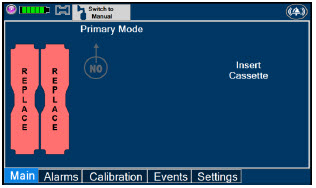
- Navigate to the "Settings" tab.
NOTE Proceed to Section 8.2.2if External Transport Mode is already enabled. 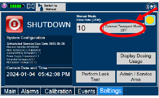
- Pressthe "External Transport Mode OFF" button.
WARNING ALWAYS ensure Consoles are placed into External Transport Mode before inserting a Cassette for external transport outside of the hospital. 
- Press"Confirm" to proceed.
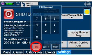
- Enter the external transport PIN.
- Press"OK" to confirm the entry.
NOTE If you do not have the PIN, contact VERO Technical Support at 877.337.4118. 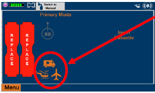
- Confirm External Transport Mode is ON.
8.2.2 Inserting an External Transport Cassette
The following steps should be taken on both Consoles. External Transport Cassettes must be used for external transport. While a Console has External Transport Mode turned ON, the Console will only allow External Transport Cassettes to preheat. If a Hospital Cassette is inserted, the Console will display an informational message and eject the Hospital Cassette (See Section 9.6).
Upon the insertion of a Cassette, a test will be initiated on the Console to check and ensure the integrity of the Water Traps and Sample Line (see Section 2.13), this helps ensure the accuracy of NO being delivered to the ventilator circuit.
ILLUSTRATION ACTION Warnings, Cautions and Notes 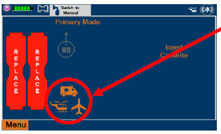
- Confirmboth Consoles have External Transport Mode ON.
WARNING ALWAYS follow Cassette inspection instructions prior to insertion. Not inspecting the Cassette prior to insertion may lead to using a faulty Cassette, resulting in injury.
ALWAYS ensure Consoles are placed into External Transport Mode before inserting a Cassette for external transport outside of the hospital.NOTE Upon turning on the Consoles, the Cassette indicator will display "Replace" 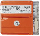
- Confirmthe Cassettes are External Transport Cassettes.
WARNING ONLY use External Transport Cassettes, identified by orange color and transport sticker, in external transport outside of the hospital. 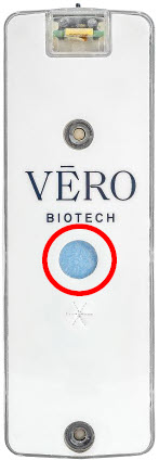
- Confirmthe Cassette State Window on eachCassette is blue.
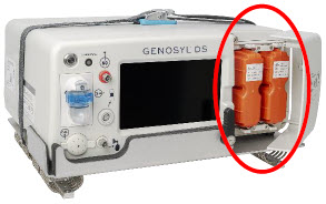
- Openthe Cassette Access Doors and inserttwo Cassettes into the Dosing Console and at least one Cassette into the Back-up Console. Push until it clicks.
NOTE Make sure Consoles are turned on before inserting the Cassette.
The Water Trap / Sample Line Leak Test is automatically initiated when the Cassette has been insertedand the measured NO is less than 1.0 ppm.
After the first Cassette is fully inserted, the Operator will have 60 seconds to close the blue Stopcock Valveto perform the test ( Step 5below). Gas lines will need to be connected to the Console in order to pass the Water Trap / Sample Line Leak Test.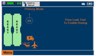
NOTE The Display Screen will temporarily indicate the Cassette has been detected, then automatically transition to the Water Trap / Sample Line Leak Test screen. 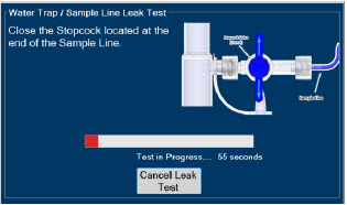
- Followthe onscreen instructions on both Consoles.
WARNING DO NOT use the Cassette if the window is not blue. A Cassette State Window that is any color other than blue may affect the Cassette's ability to provide the correct NO dosage to the patient, which may cause injury or death. NOTE The screen will indicate the Water Trap / Sample Line Leak Test has started and the progress bar will be red until the stopcock valve has been closed, upon which it will then turn green if there is no leak detected.
Pressing "Cancel Leak Test", will allow for dosing in Manual Dosing Mode. See Section 8.2.6 Using Manual Dosing Modewhile External Transport Mode is Enabled for detail around dosing in Manual Dosing Mode. Cassette is inserted front first. The Cassette State Window is not visible when properly inserted. If the Cassette State Window is not blue, see 10.8 Troubleshooting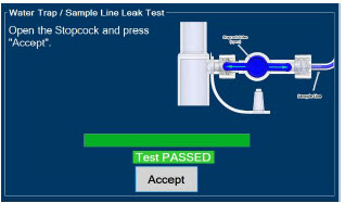
- Followthe onscreen instructions on both Consoles.
CAUTION Open the blue Stopcock Valve priorto pressing "Accept". Failure to do so will result in a line occlusion alarm. 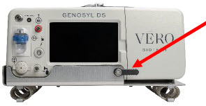
- Ensure the door latch is in the down position to keep the door closed.
8.2.3 Setting a Dose in External Transport Mode with an Adaptive Sensor
This section describes how to set a nitric oxide dose while External Transport Mode is ON, and an Adaptive Sensor is used in the patient circuit. Refer to Section 8.1.2 and 8.1.3for recommended set up diagrams.
ILLUSTRATION ACTION Warnings, Cautions and Notes 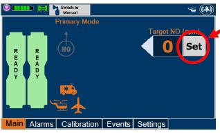
- Pressthe gray "Set" button on the display screen.
NOTE The Adaptive Sensor must detect flow through the respiratory circuit to set a dose. 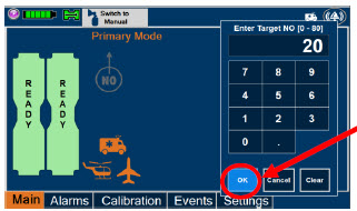
- Enterthe prescribed dose in ppm on the electronic keypad.
- Press"OK" to confirm the entry.
NOTE The time to reach target dose may vary up to 10 minutes.
If unable to set the dose in Primary Dosing Mode, see Troubleshooting, Section 10.8.NOTE If manual ventilation is required, proceed to Section 8.2.6.
When adjusting dose, proceed to Section 8.2.5.
If dosing is completed, proceed to Section 8.2.8.NOTE The display screen will look as shown after completing steps 1-3. NOTE The NO 2sensor reading may appear as "—" for the first 30 seconds of dosing while the sample system is preparing. 8.2.4 Setting a Dose in External Transport Mode without an Adaptive Sensor
This section describes how to set a nitric oxide dose while External Transport Mode is ON without an Adaptive Sensor. In the absence of an Adaptive Sensor, the GENOSYL DS will properly deliver and control nitric oxide dose. However, the user will have to manually select a Total Flow range.
ILLUSTRATION ACTION Warnings, Cautions and Notes 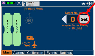
- Pressthe gray "Set" button on the display screen.
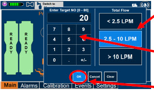
- ConfirmTotal Flow range is appropriately selected.
- Enterthe prescribed dose in ppm on the electronic keypad.
- Press"OK" to confirm the entry.
NOTE The time to reach target dose may vary up to 10 minutes.
If unable to set the dose in Primary Dosing Mode, see Troubleshooting, Section 10.8.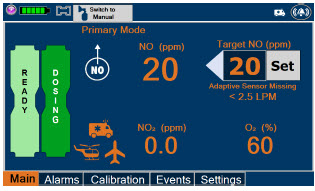
NOTE If manual ventilation is required, proceed to Section 8.2.6.When adjusting dose, proceed to Section 8.2.5.
If dosing is completed, proceed to Section 8.2.8.NOTE The display screen will look as shown after completing steps 1-4. NOTE The NO 2sensor reading may appear as "--" for the first 30 seconds of dosing while the sample system is preparing. 8.2.5 Adjusting a Dose in External Transport Mode
ILLUSTRATION ACTION Warnings, Cautions and Notes 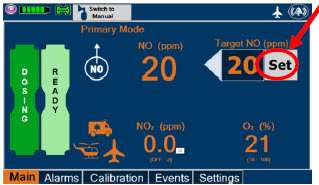
- Pressthe gray "Set" button to access the electronic keypad on the display screen on the Dosing Console.
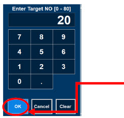
- Enterthe prescribed dose using the electronic keypad.
- Press"OK" to confirm the dose and to start dosing administration.
NOTE If dosing is completed, proceed to Section 8.2.8. 8.2.6 Using Manual Dosing Mode while External Transport Mode is Enabled
This section will describe NO administration when manual ventilation is required.
ILLUSTRATION ACTION Warnings, Cautions and Notes 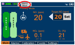
- Ensurethe oxygen flow source is set appropriately or adjust as needed.
- Pressthe button "Switch to Manual" on the Dosing Console.
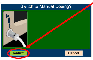
- Press "Confirm" to switch to Manual Dosing.
WARNING If the dilution flow rate displayed on the screen does not match the wall source, then the estimated NO may be inaccurate. 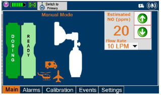
NOTE Dosing has been initiated at the same dose (ppm) as set in Primary Dosing Mode.
If the primary dosing was set at "0" prior to pressing the "Switch to Manual" button, the estimated NO will also be at "0" and will need to be adjusted.
If the dose was set between 1 and 5 ppm prior to pressing the "Switch to Manual" button, the estimated NO dose will be at "5 ppm" and may be adjusted.
In the event dose is initiated in Manual Dosing Mode, the console will default to 20 ppm, which can be adjusted as needed.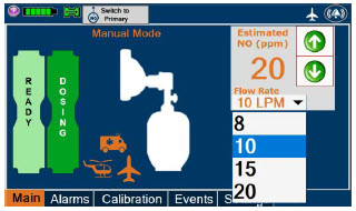
- To resumeprimary dosing, see Section 8.2.7.
NOTE If an adjustment of the NO concentration is required, press the green up and down arrows.
If an adjustment to the dilution flow rate is required while in Manual Dosing Mode, press the LPM value and a drop-down menu will expand. Press the prescribed value. The new value will be highlighted in blue and the drop-down menu will collapse.8.2.7 Resuming Primary Dosing while in External Transport Mode
This section describes the process for resuming primary dosing from Manual Dosing Mode.
ILLUSTRATION ACTION Warnings, Cautions and Notes 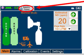
- Pressthe "Switch to Primary" button at the top of the Manual Dosing Mode screen.
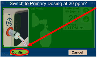
- Press"Confirm" to start dosing or "Cancel" to cancel.
NOTE The NO dose used in Manual Dosing Mode will become the set target dose in Primary Dosing Mode. 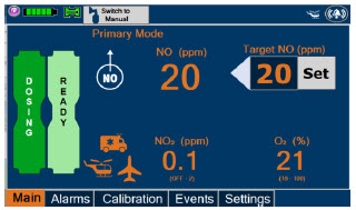
NOTE The display screen will look as shown after completing steps 1-2. 8.2.8 Console Shutdown while in External Transport Mode
WARNING NEVER turn the rear power switch OFF until the System has gone through a controlled shutdown or instructed by VERO Technical Support. Turning the rear power switch OFF prematurely (e.g., while it is still in use) will immediately shut down the device. This may result in interruption in NO delivery to the patient, which may cause injury or death. CAUTION NEVER turn the rear power switch OFF until the System has gone through a controlled shutdown or instructed by VERO Technical Support. Turning the rear power switch OFF prematurely (e.g., while it is still in use) will immediately shut down the device and may cause improper operation upon restart. NOTE - It is recommended that the Console be rebooted at least once every 30 days.
- If a Console is shutdown with External Transport Mode ON, External Transport Mode will remain ON when the Console is rebooted.
If the administration of NO must be stopped, then the dose must be set to "0". The following procedure describes how to remove the Cassettes and the following section will describe how to shut down the Console.
DISPLAY ACTION Warnings, Cautions and Notes 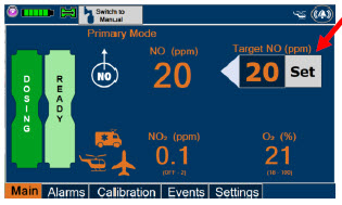
- Pressthe gray "Set" button to access the electronic keypad on the display screen.
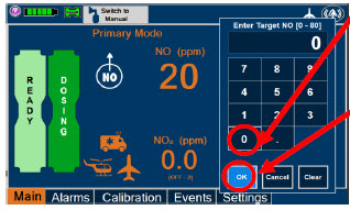
- Setthe dose to "0" using the electronic keypad.
- Press"OK" to confirm the entry.
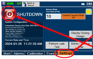
- If the "Settings" tab is not displayed, pressthe "Menu" tab to access the sub-level tabs.
- Pressthe "Settings" tab on the display menu.
- Pressthe red "System Shutdown" icon.
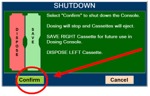
- Reviewon screen prompt.
- Press"Confirm" to shutdown Console.
- Waituntil the Console shuts down, the display screen appears blank, and the Console emits an audible beep.
NOTE If the System does not shut down, see Troubleshooting Section 10.8.
The screen will inform user if Cassette should be saved or disposed of. Refer to Section 2.14Shutdown Cassette Status Indicator description.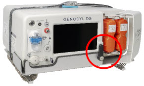
- Openlatch and Cassette Access Door.
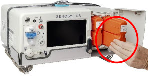
- Removethe Cassettes by pulling the Cassette straight out and check the Cassette Status Indicator for usability
- Savethe unused Cassette for future use. Disposethe inerted Cassette per hospital policy.
NOTE The Console will inert any remaining contents from a dosing Cassette upon ejection, rendering it unusable. If a Cassette has only been preheated, and not used for dosing, the contents have not been inerted and it can still be used. The Cassette State Window will remain blue on Cassettes that have not been inerted. 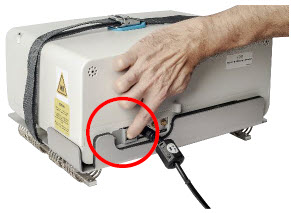
- Pressthe Black Rocker Power Switch to the "OFF" position.
- Repeatsteps 1-13 for the other Console.
WARNING NEVER turn the rear power switch OFF until the System has gone through a controlled shutdown or instructed by VERO Technical Support. Turning the rear power switch OFF prematurely (e.g., while it is still in use) will immediately shut down the device. This may result in interruption in NO delivery to the patient, which may cause injury or death. CAUTION NEVER turn the rear power switch OFF until the System has gone through a controlled shutdown or instructed by VERO Technical Support. Turning the rear power switch OFF prematurely (e.g., while it is still in use) will immediately shut down the device and may cause improper operation upon restart. 8.2.9 Switching External Transport Mode OFF
Both the Dosing Console and the Back-up Console must have External Transport Mode OFF before dosing with Hospital Cassettes in the hospital setting.
DISPLAY ACTION Warnings, Cautions and Notes 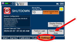
- Navigateto the "Settings" tab.
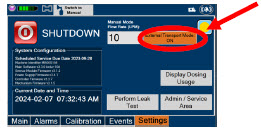
- Pressthe "External Transport Mode ON" button.

- Select"Confirm" on the screen.
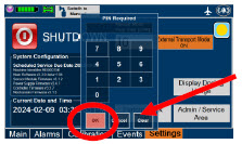
- Enterthe external transport PIN.
NOTE If you do not have the PIN, contact VERO Technical Support at 877.337.4118 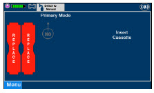
- ConfirmExternal Transport Mode is OFF.
GENOSYL ®DS
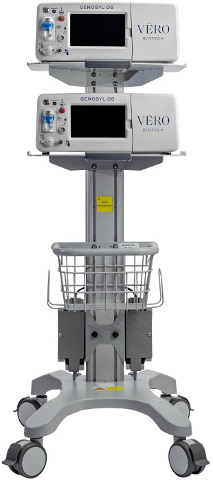
SECTION 9
USE WITH ANESTHESIA GAS MACHINE9. USE WITH ANESTHESIA GAS MACHINES
WARNING - ALWAYS use the GENOSYL DS in accordance with the indications, usage, contraindications, warnings, and precautions described in the GENOSYL prescribing information and labeling. Refer to latest approved prescribing information and labeling prior to use.
- ALWAYS use the Anesthesia Gas Machine (AGM) in accordance with the manufacturer's instructions.
- The approved patient population for the GENOSYL DS as specified in the drug labeling for GENOSYL (nitric oxide for inhalation (iNO)) is limited to neonates. The GENOSYL DS is not intended to be used in other patient populations.
CAUTION Rebreathing validation testing was performed with semi-closed breathing systems. Non-rebreathing validation testing was performed with semi-open breathing systems. The GENOSYL DS has not been evaluated with fully open or fully closed anesthesia breathing systems. NOTE - The GENOSYL DS performs as specified in this Operator's Manual independent of anesthetic agent, anesthetic agent concentration, and fresh gas flow rate.
- Changes in the AGM ventilator settings, fresh gas flow rate, or pushing the Oxygen Flush button by the user may cause brief transient changes in the measured NO value.
- Use of an Adaptive Sensor is recommended for use with AGMs. If not using an Adaptive Sensor:
- And using rebreathing fresh gas flow rates, it is recommended that the < 2.5 LPM Total Flow setting be selected.
- And using non-rebreathing fresh gas flow rates, it is recommended that the Total Flow selection based on the minute volume be selected
Compatibility testing has demonstrated performance meeting requirements for the GENOSYL DS operating range of 0 to 80 ppm with the following anesthesia gas machines at the operating ranges shown in Table 5for both mechanical and manual AGM ventilation modes. Fresh gas flow rates between 0.5 LPM and 15 LPM (10 LPM maximum tested when rebreathing), and I:E ratios ranging from 1:2 to 1:4 were validated. At low breath rates and high tidal volume settings, NO doses above 60 ppm could result in elevated NO2 levels.
See Section 12.2 Table 14for modes validated for each anesthesia gas machine.
- Drӓger Fabius GS
- Drӓger Fabius GS Premium
- Drӓger Fabius Tiro
- GE Healthcare Aisys CS2
CAUTION - The Adaptive Sensor is recommended for use with anesthesia gas machines (AGMs). When using an AGM without the Adaptive Sensor, transient dose excursions outside of the set NO dose may occur during Cassette transition, and changes in breathing circuit flow may cause fluctuations in measured levels of NO and NO 2when using the manual ventilation bag integrated with the AGM.
- When using anesthesia gas machines, NO 2levels may exceed 3.0 ppm when dosing ≥ 58 ppm NO into 100% FiO 2, resulting in nitric oxide delivery interruption. Once sample value of NO 2is below 3.0 ppm, the Console will auto resume delivery of NO at set dose.
Table 5: Anesthesia Gas Machine Validation Compatibility Test Ranges * Setting Range Unit - * Inspiratory Flow Rate is not measured by Anesthesia Gas Machines.
- † If testing range is higher than the max setting of the Anesthesia Gas Machine, the highest setting available was tested.
Respiratory Rate 6-60 BPM Peak Inspiratory Pressure † 0-70 cmH 2O Positive End Expiratory Pressure 0-20 cmH 2O Specific use cases may require the use of an Inline Mixer which is used to mix the NO gas with the gas supplied by the AGM through a filter containing silica gel to provide intra-breath NO delivery for certain scenarios. Refer to Table 6below for use case scenarios.
Table 6: Anesthesia Gas Machine Tidal Volume Use Cases Manufacturer Model Fresh Gas Flow
(FGF)Ventilator Range Tested: Neonatal Ventilator Range Tested: Pediatric/Adult Ventilator Circuit Using Injection Assembly
( Ref. Fig. 30)Ventilator Circuit Using Injection Assembly
( Ref. Fig. 30)Ventilator Circuit Using Mixer Assembly (With Inline Mixer, Ref. Fig. 31) Key
: Range fully tested
N/A: Use of Mixer is not recommended
VT: Tidal VolumeDrӓger Fabius GS
Fabius GS
Premium
Fabius TiroFGF > 0.75 LPM VT ≤ 200 ml VT > 200-500 ml FGF ≤ 0.75 LPM N/A GE Healthcare Aisys CS2 FGF > 0.75 LPM VT ≤ 300 ml VT > 300 – 585 ml FGF ≤ 0.75 LPM N/A 9.1 Connection to a Dual Limb Anesthesia Circuit
The validated anesthesia circuit configurations are indicated in Table 6above and an illustrated circuit diagram is presented in Figures 30 and 31. For additional instructions on System set-up, refer to Section 3.5GENOSYL DS Gas Line Connections, Section 4System Start up, and Section 5Nitric Oxide Administration.
NOTE Connections to various AGMS are unique to each manufacturer as well as their corresponding disposable circuits. CAUTION DO NOT use in environments with <20% relative humidity (RH) in the absence of supplemental humidification. Prolonged use in dry environments without humidification will damage the gas sensors. GENOSYL DS was validated with listed AGMs using a Heat Moisture Exchanger (HME) and was not tested with heated humidification connected to the respiratory circuit. 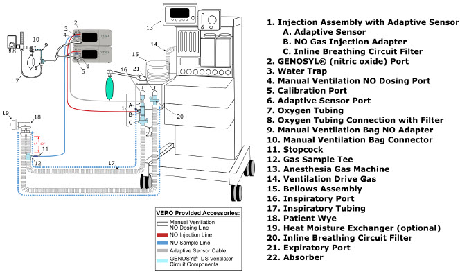
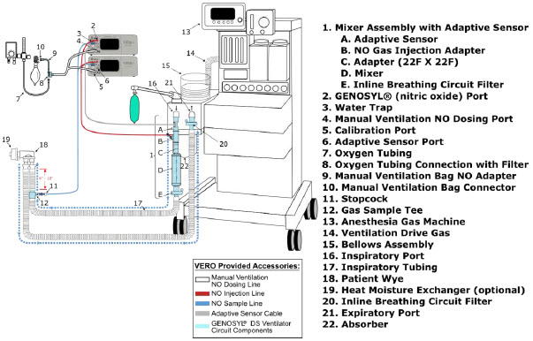
9.2 Connection Instructions for the GENOSYL DS to an Anesthesia Gas Machine
WARNING - The flow out of the anesthesia gas machine via the INSPIRATORY breathing circuit limb must pass through the GENOSYL DS Gas Injection Assembly.
- The GENOSYL DS injects and samples gas from the patient respiratory circuit which may affect the triggering sensitivity of the anesthesia gas machine (AGM). ALWAYS ensure the trigger sensitivity of the AGM is checked after connecting the GENOSYL DS to the breathing circuit and starting iNO delivery or when the dose is changed and adjust trigger sensitivity as necessary. Failure to do so may lead to AGM auto cycling or apnea alarm.
- ALWAYS ensure the patient disconnect and high–pressure alarms are used with the AGM.
NOTE - A dual limb anesthesia breathing circuit should be used for iNO delivery with the GENOSYL DS.
- The GENOSYL DS Sample Line must be placed on the INSPIRATORY limb of the breathing circuit between 6 and 12 inches from the patient wye. If the sampling line is placed greater than 6 inches from the patient wye it minimizes the sampling of mixed inspired/expired gas concentrations and if placed less than 12 inches from the patient wye it ensures correct iNO and NO 2measurement.
DISPLAY ACTION Warnings, Cautions and Notes 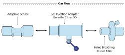
- Connectthe Inline Breathing Circuit Filter to the Gas Injection Adapter (22 mm ID × 22 mm OD).
- Connectthe Adaptive Sensor to the inlet end of Gas Injection Adapter (22mm ID × 22 MM OD).
NOTE For detailed Injection Assembly with Adaptive Sensor instructions, refer to Section 3.4.1. If an Inline Mixer is required per Table 6,refer to Section 3.4.2for instructions to assemble and then proceed to Step 2. 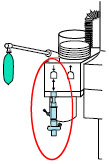
- Attachthe Injection Assembly with Adaptive Sensor to the Gas Injection Adapter on the Inspiratory Port on the AGM.
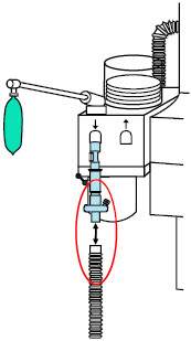
- Attachthe inspiratory limb of the breathing circuit to the Inline Breathing Circuit Filter. If the breathing circuit has a Sample Gas Tee inserted, ensure this limb of the circuit is attached to the Inline Breathing Circuit Filter.
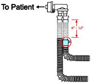
- Insertthe Gas Sample Tee into the inspiratory limb of the breathing circuit, 6-12" from the patient wye.
WARNING Ensure the Injection Assembly and the Gas Sample Tee are BOTH inserted on the inspiratory limb of the circuit. NOTE Skip this step if a Gas Sample Tee is already connected and in-line with the circuit. 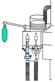
- Insertan Inline Breathing Circuit Filter between the Expiratory Port and expiratory limb. Skip this step if a bacterial filter is already present in the expiratory limb of the breathing circuit.
NOTE Skip this step if a bacteria filter is already connected and in-line with the circuit. 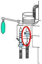
- Attachthe expiratory limb of the breathing circuit to the Inline Breathing Circuit Filter on the Expiratory Port on the Anesthesia Machine
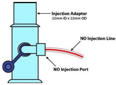
- Push and twistclockwise the luerlock collar from the NO injection line onto the NO injection port of the Gas Injection Adapter on the Injection Assembly.
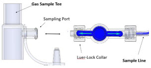
- Push and twistclockwise the Luer-Lock Collar of the Stopcock on the Sample Line onto the Sampling Port of the Gas Sample Tee.
NOTE Refer to Section 4for Console Start up instructions and Section 5for nitric oxide administration instructions. 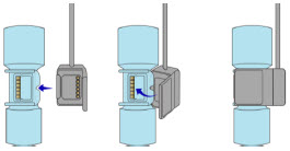
- Connectthe distal end of the Adaptive Sensor Cable to the Adaptive Sensor on the Injection Assembly
- Refer to Section 3.6for connection instructions of the GENOSYL DS to a manual bagging system.
NOTE - When using the manual ventilation bag integrated with the AGM, nitric oxide can be delivered by leaving the Console in Primary Dosing Mode. Nitric oxide will be delivered through the Injection Assembly into the anesthesia gas circuit.
- In the event of anesthesia gas machine failure, NO delivery can be continued using Manual Dosing Mode on the GENOSYL DS with a manual bag connected to the manual ventilation port on the front of the Console and an alternative gas source than the AGM. Refer to Section 3.6for GENOSYL DS connection instructions and Section 5.4for GENOSYL DS Manual Dosing Mode operating instructions.
GENOSYL ®DS
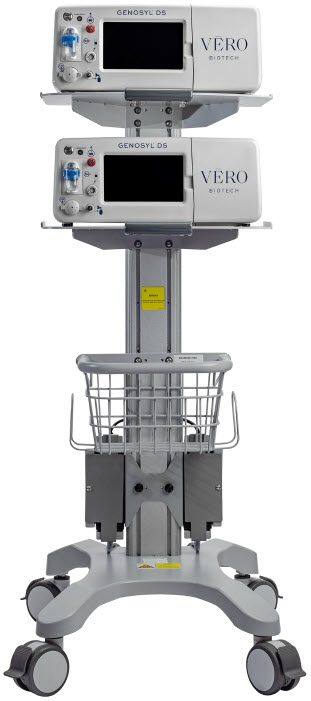
SECTION 10
ALARMS, ALERTS, AND TROUBLESHOOTING10. ALARMS, ALERTS, AND TROUBLESHOOTING
WARNING ALWAYS ensure patient safety before troubleshooting (such as an activated alarm) or replacing a problematic item. Not monitoring the patient prior to attending to an alarm can result in injury or death. 10.1 Alarms, Alerts, and Troubleshooting
This section contains the System alarms and messages in order of High (red), Medium (yellow), and Low Priority (turquoise) followed by Informational Messages (green). The table shows the alarm/symptom, the possible cause(s) of the alarm and recommended action to resolve the alarm. If the alarm/issue cannot be resolved, contact Technical Support at 877-337-4118.
A sample screen with an active alarm is shown below:
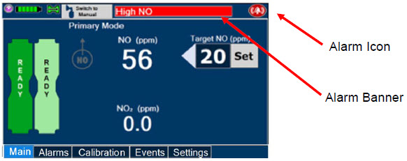
The alarm banner contains a drop-down menu containing a list of all alarms should there be multiple activated. Tapping the alarm banner will open the VERO On-screen Troubleshooting module (See Section 10.2). The alarm icon is always present on the top right of the screen and tapping the icon will pre-silence or silence alarms. Refer to the table below for descriptions of each alarm status:
Table 7: Alarm Icon Descriptions ALARM ICON DISPLAY DESCRIPTION 
No active alarm condition is detected on the Console. Tap this icon to activate the Pre-Silence feature. 
Alarms are actively pre-silenced. Countdown of time remaining appears under the icon. Pre-silence lasts for 120 seconds. Low/High NO, High NO 2, Low/High O 2, Water Trap Removed, and Dosing Cassette Removed alarms are pre-silenced. Alarms will still be visible on alarm banner but audible alarm will not sound. 
Console has an active alarm condition that requires attention. Tap the icon to silence the alarm for 120 seconds. 
Console has an active alarm condition that requires attention and the alarms have been silenced. Countdown of time remaining for silence appears on bottom of icon. The alarm order, color, and audio signal will follow the highest priority alarm.
Table 8: Alarm Characteristics Alarm Priority Color Flashing Frequency Flashing Duty Cycle Sound Level High Red 1.4 to 2.8 Hz 40-60% 79.8 dBA Medium Yellow 0.4 to 0.8 Hz 40-60% 76.1 dBA Low Turquoise Constant (on) 100% 63.3 dBA Some alarms may be adjusted within the "Alarms" tab. See Table 9below for adjustment characteristics. The System will always resort to the original default alarm settings upon reboot or complete power failure.
In addition, the System has a fallback safety dose interruption feature which will temporarily interrupt delivery of NO when the sensors detect a sampled value of ≥ 100 ppm NO and/or ≥ 3 ppm NO 2. The System will resume NO dosing after dissipation of high gases without operator input.
Review Table 9for complete details about the alarm adjustment ranges, defaults, alarm activation timing and interruption conditions.
Table 9: Alarm Ranges, Defaults and Dose Interruption Condition Alarm Adjustment Range Default Setting Alarm Activation Interruption Condition High NO (ppm) 0 – 100 ppm + 50% of set value or 2 ppm (Whichever is greater) 10 minutes after dose
>0 ppm entered≥ 100 ppm Low NO (ppm) 0 – 99 ppm - 50% of set point. For doses less than 4ppm, setting ranges between -50 - 70% of set point 10 minutes after dose
>0 ppm enteredNA High NO 2(ppm) 1-2.9 ppm 2 ppm 30 seconds after dose
> 0 ppm entered≥ 3 ppm High O 2(% v/v) 22 – 100 ppm 100 ppm Immediately after dose
> 0 ppm enteredN/A Low O 2(% v/v) 18 – 99 ppm 18 ppm Immediately after dose
> 0 PPM enteredN/A NOTE The safety dose interruption feature is active immediately upon setting a dose greater than 0 ppm. The NO and NO 2alarms do not need to be active for the safety dose interruption feature to be activated. Alarms are legible for a person with 20/20 vision at a distance of 1 meter when viewed directly on the screen.
An alarm history indicating the date, time, and type of alarm can be viewed by selecting the "Alarms" tab and then selecting the alarms history button. The alarm history can be cleared by pressing the "Clear Alarm" button. If the alarm history reaches capacity, the oldest alarms will begin rolling off and become non-visible to the user. Upon Console shut down or power loss, the alarm log is cleared. If the alarm log is cleared, or reaches capacity, history of alarms will still be recorded in permanent memory accessible when logged in as admin. The operator of the equipment should be physically in front of the Console while interacting with the System. During NO delivery, the operator should remain within visual and auditory distance of the System.
The alarm system is automatically tested during the initial power-on self-test with an audible beep to confirm successful completion. Should there be an issue with communication to the alarms system electronics, a Hardware Failure error message will appear at the end of the self-test.
10.2 On-screen Troubleshooting Module
The GENOSYL DS features on-screen troubleshooting support for specific alarm conditions (refer to Table 10for a list of alarms where on-screen troubleshooting support is available). This module can be accessed by tapping an active alarm banner or by selecting the "Alarm Info" button on the "Alarms" tab. If no alarm condition is active, and the module is accessed via the "Alarms" tab, a menu will be presented to select which condition the user would like to view troubleshooting steps for. Refer to Figure 32for a view of the menu. If an alarm condition is active, the module will open directly to recommended troubleshooting actions, if available. Refer to Figure 33for a description of navigating the module. If the user cannot address the alarm condition using the module, the user will be instructed to consider switching to the Back-up Console and should contact Technical Support.
Table 10: Alarm conditions included in On-screen Troubleshooting Module Alarm Condition Low NO Line Occlusion Delivery Flow Error High Back Pressure 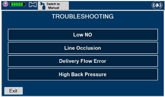
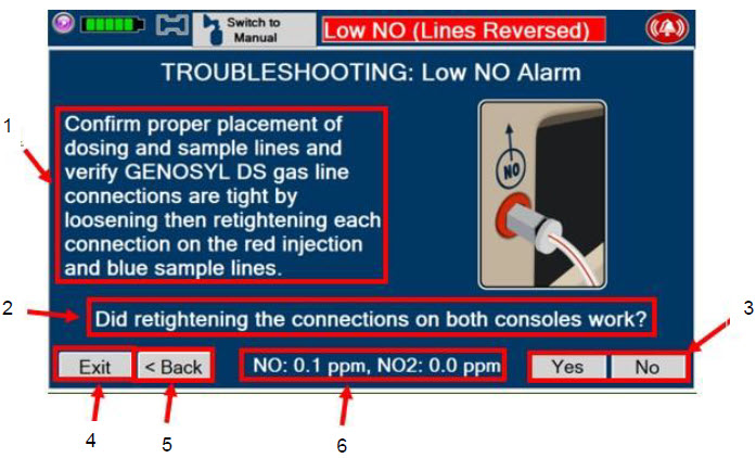
- Recommend action to address alarm condition
- Question to confirm if recommended action addressed active alarm condition.
- Yes/No to answer if recommended action addressed alarm condition. Pressing "Yes" will exit the module. Pressing "No" will advance to the next recommended action.
- "Exit" button will exit the module.
- "Back" button will bring user to the previous screen (previous recommended action).
- NO and NO 2values will display on this portion of the screen.
Figure 33: Description of VERO On-screen Troubleshooting Module Navigation 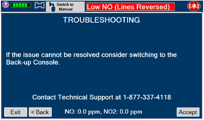
10.3 High Priority Alarms and Messages
High priority alarms and messages will have a red background and be accompanied by an audible alarm. These alarms and messages require immediate operator response.
High Priority Alarms and Messages Alarm/Message Possible Cause Recommended Action Nitric Oxide Delivery Interruption due to High NO
Message Box:
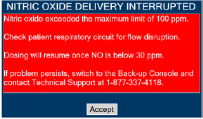
- Respiratory circuit flow changed abruptly
- Low or no flow
- in patient respiratory circuit
- Condensation
- Cause not determined
This fallback mode will be cancelled once the nitric oxide level drops below the set dose + 50%. - Verify flow is present in the patient's respiratory circuit.
- Allow time for the sensor measurement to adjust while completing the next steps.
- Verify GENOSYL DS gas line connections are tight by loosening then retightening each connection on the red injection and blue sample lines.
- Verify proper placement of injection assembly and sample adapter within the respiratory circuit.
- Replace adapters that have evidence of excessive condensation.
- If the sensor measurement does not adjust, switch to Back-up Console.
- Contact Technical Support.
Banner:

Screen Display:
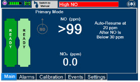
Nitric Oxide Delivery Interruption due to High NO 2
Message Box:
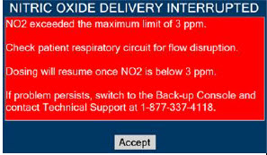
- Low or no flow in patient respiratory circuit
- Respiratory flow changed abruptly
- Leak in patient respiratory circuit
- Condensation
- Bias flow on respiratory device is too low
- Cause not determined
This fallback mode will be cancelled once the NO2 level drops below 3 ppm. - Verify flow is present in patient's respiratory circuit.
- Consider increasing bias flow, if applicable.
- Allow time for the sensor measurement to adjust while completing the next steps.
- Verify GENOSYL DS gas line connections are tight by loosening then retightening each connection on the red injection and blue sample lines.
- Verify proper placement of injection assembly and sample adapter within the respiratory circuit.
- Replace adapters that have evidence of excessive condensation.
- If the sensor measurement does not adjust, switch to Back-up Console.
- Contact Technical Support.
Banner:

Screen Display:
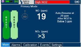
High NO Alarm Message Box:
None- Respiratory circuit flow changed abruptly
- Low or no flow in patient respiratory circuit
- High NO alarm may be inappropriately set
- Condensation
- Cause not determined
- Verify flow is present in the patient's respiratory circuit.
- Allow time for the sensor measurement to adjust while completing the next steps.
- Verify GENOSYL DS gas line connections are tight by loosening then retightening each connection on the red injection and blue sample lines.
- Verify proper placement of injection assembly and sample adapter within the respiratory circuit.
- Replace adapters that have evidence of excessive condensation.
- Go to the Alarms screen and check the NO alarm setting. Set alarm to the desired setting.
- If the sensor measurement does not adjust, switch to Back-up Console.
- Contact Technical Support.
Banner: 
Screen Display:
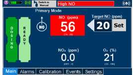
High NO 2Alarm Message Box:
None- Low or no flow in patient respiratory circuit
- Respiratory circuit flow changed abruptly
- High NO 2alarm may be inappropriately set
- Condensation
- Bias flow on respiratory device is too low
- Cause not determined
- Verify flow is present in the patient's respiratory circuit.
- Consider increasing bias flow, if applicable
- Allow time for the sensor measurement to adjust while completing the next steps.
- Verify GENOSYL DS gas line connections are tight by loosening then retightening each connection on the red injection and blue sample lines.
- Verify proper placement of injection assembly and sample adapter within the respiratory circuit.
- Replace adapters that have evidence of excessive condensation.
- Go to the Alarms screen and check the NO2 alarm setting. Set alarm to the desired setting.
- If the sensor measurement does not adjust, switch to Back-up Console
- Contact Technical Support
Banner:

Screen Display:
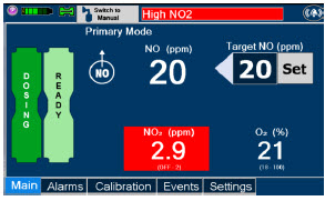
Low NO alarm Message Box:
None- Gas lines are not connected or properly placed in the respiratory circuit
- Water Trap full
- Leak in respiratory circuit
- Cassette not full inserted
- Alarm limit not adjusted properly
- NO Cassette needs to be replaced
- Cassette is depleted without a second Cassette inserted
- Gas sample tee placed too close to patient wye adapter
- Cause not determined
- Verify GENOSYL DS gas line connections are tight by loosening then retightening each connection on the red injection and blue sample lines.
- Verify proper placement of Injection Assembly and Sample adapter within the respiratory circuit.
- Ensure gas sample tee is placed 6 to 12 inches from the patient wye adapter.
- Replace adapters that have evidence of excessive condensation.
- Check the respiratory circuit for the presence of leaks.
- If not using an Adaptive Sensor, confirm total flow range is properly selected.
- Allow time for the sensor measurement to adjust while completing the next steps.
- Push on Cassette to ensure it is fully seated.
- Empty Water Trap. Replace Water Trap if necessary.
- If Cassette is depleted, insert a second Cassette if not already present. If auto transition does not occur, switch to Back-up Console.
- Ensure dose and flow are set within specifications. (see Section 12.1.4Liters per minute multiplied by ppm should not exceed 800. (Example 40 LPM × 20ppm = 800)
- Go to alarms screen and check the NO alarm setting. Set the alarm to the desired setting.
- If sensor measurement does not adjust, switch over to Back-up Console.
- Contact Technical Support.
Banner:

Calibration Required Message Box:
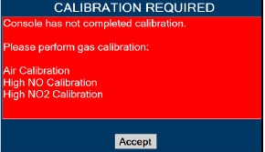
- Calibration for the sensor is required
This fallback mode will be cancelled once a successful high gas calibration has been completed. - Calibrate Console (see Section 11.1).
- If the calibration required alarm occurs after a successful calibration has been completed, contact Technical Support.
Banner:

Hardware Failure Message Box:
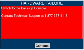
- Internal hardware damage or communication failure
In this fallback mode, the Console will continue delivering nitric oxide in an open loop mode at the last entered dose. - Switch to Back-up Console.
- Contact Technical Support.
Banner:

Hardware Failure – Power Board Message Box:

- Internal hardware damage or communication failure
- Switch to Back-up Console.
- Contact Technical Support.
Banner: 
Hardware Error During POST (Power On Self-Test) Message Box:
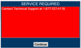
- Problem occurring during boot-up sequence
- Internal hardware damage or communication failure
- Use Back-up Console if NO delivery is needed immediately.
- Re-boot by holding Silver Power Button down for 10 seconds.
- If error message continues, contact Technical Support.
Battery Error Message Box:
None- Internal battery error or battery fails to charge
- Battery becomes disconnected
- Plug in AC power.
- Verify power connections on Console, power adapters, and AC power source.
- Verify the light on the black power supply is illuminated and green.
- If not dosing, shut down Console.
- Allow Console to charge for a minimum of 1 hour. Monitor the Charge Status Indicator on the front panel. Indicator should charge from red to green when the battery has achieved enough charge to resolve the battery error.
- Restart Console and verify if error persists.
- If error persists, allow battery to charge several more hours, or overnight.
- If alarm does not clear, switch to Back-up Console and contact Technical Support
Banner: 
Line Occlusion (Sample) Message Box:
None- Stopcock valve on the Sample Line (blue) is in the closed position
- Water Trap is full
- Blue Sample Line is kinked or occluded
- Sample Line Filter is occluded
- Cause not determined
In this fallback mode, the Console will continue delivering nitric oxide in an open loop mode at the last commanded dose until the line occlusion is resolved. - Ensure blue Sample Line Stopcock is in the open position.
- Remove Sample Line Filter, replace if needed.
- Empty Water Tap.
- If occlusion persists after emptying, replace Water Trap.
- Inspect entire length of blue sample line for kinks or occlusions.
- Replace gas lines if kink or occlusion cannot be resolved.
- If issue is still not resolved, switch over to Back-up Console.
- Contact Technical Support.
Banner: 
Line Occlusion (Cal) Message Box:
None- Obstruction to calibration port
- Calibration tank valve closed during high calibration procedure
- Cause not determined
- Ensure calibration port is free of debris or damage and nothing is connected.
- Perform high calibration by following procedure in Section 11.1
- If issue is still not resolved, switch over to Back-up Console.
- Contact Technical Support
Banner:

Cassette Removed while dosing Message Box:
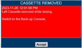
- Cassette manually ejected using emergency ejection tabs
- Hardware damage which causes the System to not be able to detect the Cassette
- Cause not determined
- If secondary Cassette is not inserted, transition to Back-up Console
- Contact Technical Support.
Banner:
NoneWater Trap Not Detected Message Box:
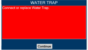
- Water Trap not seated properly
- Water Trap not present
- Cause not determined
In this fallback mode, the console will continue delivering nitric oxide in an open loop mode at the last commanded dose until the water trap is replaced and the leak check is passed. - Re-seat Water Trap.
- Insert new Water Trap.
- Switch over to Back-up Console.
- Contact Technical Support.
Banner:

Configuration Parameters Incorrect
Message Box:
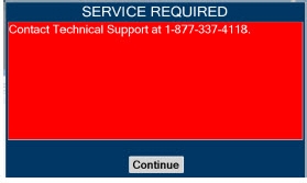
- File integrity issue
- Use Back-up Console if NO delivery is needed immediately.
- Contact Technical Support.
Battery Not Detected during POST (Power On Self- Test) Message Box:
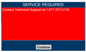
- Battery is not connected properly or not operational
- Use Back-up Console if NO delivery is needed immediately.
- Contact Technical Support.
Hardware Error During POST (Power On Self-Test) Message Box:
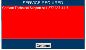
- Hardware failure occurred
- Use Back-up Console if NO delivery is needed immediately.
- Contact Technical Support.
Banner:

Cassette Not Operational Message Box:
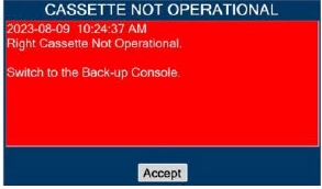
- Hardware failure within Cassette during dosing
If a secondary Cassette is inserted in the other slot, the Console will automatically switch to the secondary Cassette in this fallback mode. - If a secondary Cassette is not inserted in the other slot, switch to Back-up Console.
- Replace Cassette in original Dosing Console
- If issue is not resolved, switch to Back-up Console.
- Contact Technical Support.
System has not Completed Calibration
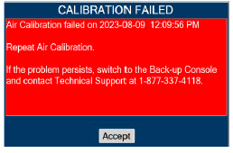
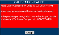
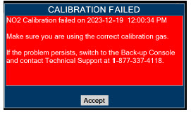
- Calibration was not completed
- Wrong/empty calibration gas tank used
- Calibration tubing is incorrectly connected to the sample port
- Failed Gas Sensor
- Calibration tank does not have enough PSI
- Kink or occlusion in calibration tubing.
- Break or crack in calibration tubing or cal gas tee
- Calibration tubing is incorrectly connected to the sample port.
- Calibration regulator is missing a washer.
- Accept message.
- Obtain correct/full calibration gas tank.
- Verify there is adequate gas present in cal tank to complete calibration (>500 PSI).
- Connect calibration tubing to Cal port.
- Verify the cal gas extension line and gas tee are free from breaks, cracks, kinks or occlusions.
- Verify presence of washer and that it is properly seated between calibration.
- Perform gas calibration. See Calibration Section 11.1.
- If you continue to have problems, contact Technical Support.
Hardware Failure while Dosing in Manual Dosing Mode – No Dose Change Message Box: 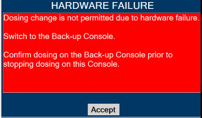
- Internal hardware damage or communication failure
In this fallback mode, the Console will continue delivering nitric oxide in an open loop mode at the last entered dose. User will not be able to adjust set dose. - Switch to Back-up Console.
- Contact Technical Support.
Banner:

Hardware Failure while Dosing–Cannot Change Dosing Modes Message Box: 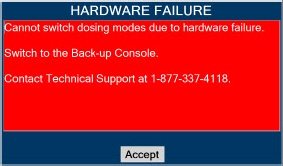
- Internal hardware damage or communication failure
In this fallback mode, the Console will continue delivering nitric oxide in an open loop mode at the last entered dose. User will not be able to switch between Dosing Modes (Primary and Manual Dosing Mode) - Switch to Back-up Console.
- Contact Technical Support.
Banner:

10.4 Medium Priority Alarms and Messages
Medium priority alarms and messages will have a yellow background. Medium priority alarms and messages require a prompt response from the operator.
Medium Priority Alarms and Messages Alarm/Message Possible Cause Recommended Action Low Battery Alarm Message box: None
Banner:

- Battery is low
- Verify power connections on console, power adapters, and AC power source.
- If AC power is not available, switch to Back-up Console.
- Then plug into AC power as soon as possible.
Cassette Failure Alarm
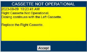
- Internal Cassette issue
- Replace with a new Cassette.
- If unresolved, switch to Back-up Console and contact Technical Support.
Service Due Date Expired
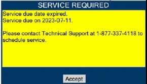
- Service date is past due
- Accept message.
- To schedule service, contact Technical Support.
- Schedule every 24 months.
Cassette to Expire in 1 Hour

- Cassette will deplete in 1 hour
- Ensure secondary Cassette is inserted and ready.
- Replace Cassette once transition is complete.
Low O 2
Message box: none
Banner:

- Respiratory device setting is incorrect
- Alarm setting is incorrect
- Ventilator flow is too low
- Verify respiratory device setting is correct.
- Set the alarm ranges to the correct setting.
- Calibrate Console (see Section 11.1).
- If sensor measurement does not adjust, switch over to Back-up Console.
- Contact Technical Support.
High O2
Message Box: none
Banner:

- Respiratory device setting is incorrect
- Alarm setting is incorrect
- Verify respiratory device setting is correct.
- Set the alarm ranges to the correct setting.
- Calibrate Console (see Section 11.1).
- If sensor measurement does not adjust, switch over to Back-up Console.
- Contact Technical Support.
Delivery Flow Error
Message Box:
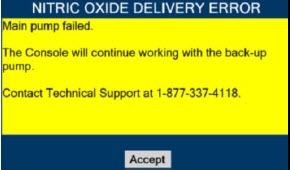
- Red injection line is kinked or occluded
- Kink or occlusion in respiratory circuit
- NO port is occluded
- Excess pressure in respiratory circuit
- Hardware issue caused a failure
- Inspect entire length of red injection line for kinks and occlusions.
- Insect respiratory circuit for kinks or occlusions
- Inspect NO output port on front of console for debris or damage.
- Ensure the air intake is not blocked.
- Resolve the kink or blockage.
- If in Manual Dosing Mode, ensure flow to patient matches selected flow on GENOSYL.
- If problem persists, contact Technical Support.
Banner:

High Back Pressure
Message Box:
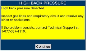
- Kinks or occlusions in the respiratory circuit.
- Inspect respiratory circuits for kinks or occlusions.
- Resolve the kink or blockage.
- If problem persists, contact Technical Support.
Banner:

Incorrect Cassette
Message Box:
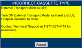
- External Transport Cassette has been inserted while External Transport Mode is OFF.
- Identify if the intended environment is Hospital or External Transport.
- If Hospital, insert Hospital Cassette to dose.
- If External Transport, turn External Transport ON. See Section 8.2.1.
- If problem persists, contact Technical Support.
Incorrect Cassette
Message Box:

- Hospital Cassette has been inserted while External Transport Mode is ON.
- Identify if the intended environment is Hospital or External Transport.
- If Hospital, turn External Transport OFF. See Section 8.2.9.
- If External Transport, insert External Transport Cassette to dose.
- If problem persists, contact Technical Support.
10.5 Low Priority Alarms and Messages
A low priority message will have a turquoise background. A low priority message will require that the operator is aware of the condition.
Low Priority Messages and Alarms Alarm/Message Possible Cause Recommended Action Nitric Oxide Delivery Interruption due to Flow Not Detected
Message Box:
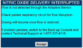
- Adaptive Sensor not detecting flow
- Cause not determined
Once flow is detected through the Adaptive Sensor, dosing will resume automatically and this fallback mode will be cancelled. - Verify proper connection of Adaptive Sensor to respiratory circuit
- Verify flow is present in the respiratory circuit
Screen Display:
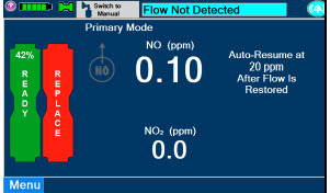
System Running on Battery Only
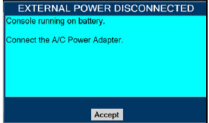
- AC power is not connected
- Check the AC power connection.
- Verify power connections on Console, power adapters, and AC power source.
- If connecting to AC power does not resolve issue, switch to Back-up Console and contact Technical Support.
Service Due Date Within 2 Days
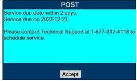
- Service date is scheduled within 2 days
- Accept message.
- Contact Technical Support to have System serviced at earliest convenience.
10.6 Informational Messages
Informational messages will have a green background. These messages require that the user is notified of the condition.
Informational Messages Alarm/Message Possible Cause Recommended Action Calibration Due within 48 Hours
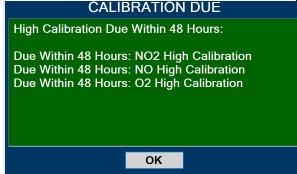
- Calibration is required within 48 hours
- Accept message.
- Perform gas calibration if desired. See Calibration Section 11.1.
Service Due Date Within 14 Days
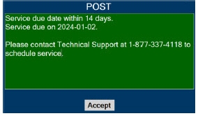
- Service date is scheduled within
- 14 days
- Accept message.
- Contact Technical Support to have System serviced at your convenience.
Cassette Will Expire In 2 Hours

- Cassette will expire within 2 hours and no secondary Cassette inserted
- Insert secondary Cassette.
- Replace Cassette once transition is complete.
Calibration Due
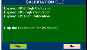
- Calibration due date has passed
- Perform gas calibration. See Calibration Section 11.1.
Invalid External Transport password

- Invalid External Transport password
- Input correct password.
- If problem persists, contact Technical Support.
Turn External Transport Mode ON

- Confirm External Transport Mode is ON
- Press "Confirm" to turn External Transport Mode ON. PIN required.
- Press "Cancel" to keep External Transport Mode OFF.
Turn Transport Mode OFF
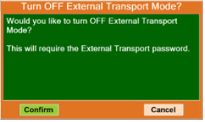
- Confirm External Transport Mode is OFF
- Press "Confirm" to turn External Transport Mode OFF. PIN required.
- Press "Cancel" to turn External Transport Mode ON.
Cassette present while switching to or from External Transport Mode

- Cassette in Console while switching to or from External Transport Mode
- Press "Eject" to remove the Cassette and switch to or from External Transport Mode. See Section 8.2.1
- Press "Cancel" to discontinue.
Cannot dose while switching to or from External Transport Mode

- Dosing while switching to or from External Transport Mode
- Press "Accept."
- Complete Dosing.
- Set Dose to 0.
- Once completed, see Section 8.2.1to enable External Transport Mode or see Section 8.2.9to disable External Transport Mode.
The gauss alarm will sound if the GENOSYL DS is too close to the MR Scanner. If the gauss alarm sounds, move the GENOSYL DS away from the MR scanner until the gauss alarm stops sounding.
WARNING ALWAYS move System away from the MR scanner if the gauss alarm sounds. The gauss alarm will sound if the System is too close to the MR scanner. Move System away from the MR scanner until the gauss alarm stops sounding. The table below provides resolutions to issues that may be encountered with the GENOSYL DS.
Issue/Symptom Possible Cause Recommend Action Screen does not turn on - Battery discharged and not connected to AC power
- Screen malfunction
- Ensure power is properly connected in the back of the unit and the wall outlet. Green light on power supply should be on.
- Ensure battery is connected properly.
- Wait for System to charge.
- Power on System.
- If not resolved, switch to Back-up Console and contact Technical Support.
Cassette does not insert properly within Console - Drop or other physical damage
- Discard damaged NO Cassette and replace with new Cassette.
- If new Cassette does not insert properly, switch to Back-up Console and contact Technical Support.
Cassette State Window is not blue - Drop or other physical damage
- Cassette was previously activated
- Discard damaged Cassette and replace with new Cassette.
Pumps are louder than normal - Enclosure damage
- Pump malfunction
- Contact Technical Support.
Cannot set dose in Primary Dosing Mode - Flow not detected through Adaptive Sensor
- Water Trap/ Sample Line Leak Test was not performed
- Calibration is required for at least one sensor
- Verify flow is present in patient circuit.
- Perform Water Trap/ Sample Line Leak Test if not already performed.
- Perform calibration if required.
- If issue is not resolved, contact Technical Support.
Console does not shutdown - Operating System issue or file corruption
- Hold the Silver power button on the front down for approximately 10 seconds. The Console should shutdown.
- If the above does not work, power the Console off with the switch on the back.
- Contact Technical Support if the issue remains.
Audible alarm tone does not sound after boot-up process - Speaker hardware failure
- Contact Technical Support.
Failed Water Trap / Sample Line Leak Test - Incorrectly connected the Sample Line to the CAL Port
- Test timed out at 60 seconds
- Sample line valve not closed properly
- Loose gas lines connections
- Water Trap not sealed completely
- Water Trap seal leak
- Ensure proper line connections.
- Conduct test within 60 seconds.
- Move the blue stopcock to the closed position.
- Check Water Trap seal.
- Replace Water Trap.
- If issue is not resolved, contact Technical Support
Cassette does not automatically eject from Console - Mechanism malfunction
- Open Cassette Access Door. Simultaneously push the tabs above and below the Cassette to manually eject the Cassette.
Screen Unresponsive - Screen is frozen
- Switch to Back-up Console.
- Hold Silver Power Button for 10 seconds.
- Wait for Console to shut down.
- Switch off and on black rocker switch.
- Reboot Console.
Adaptive Sensor Not Detected - Adaptive Sensor Cable Not Connected
- Adaptive Sensor not Connected to Adaptive Sensor Cable
- Verify Adaptive Sensor Cable is properly plugged into front of Console and the cable is fully inserted.
- Detach the Adaptive Sensor from the Adaptive Sensor Cable.
- Wait at least five seconds.
- Reattach the Adaptive Sensor to the Adaptive Sensor Cable.
Flow Not Detected - Respiratory Device not delivering flow into circuit
- Adaptive Sensor not present in circuit
- Ensure Respiratory Device is delivering flow into circuit.
- Verify Adaptive Sensor is connected in the circuit.
Adaptive Sensor Icon is Yellow - Adaptive Sensor is not properly connected or has become disconnected
- Adaptive Sensor is malfunctioning
- Detach the Adaptive Sensor from the Adaptive Sensor Cable.
- Unplug the Adaptive Sensor Cable from the Console.
- Wait at least five seconds and reinsert the Adaptive Sensor Cable into the Console.
- Reattach the Adaptive Sensor to the Adaptive Sensor Cable.
- If problem persists, replace the Adaptive Sensor.
- If problem still persists, contact Technical Support.
Higher than desired NO 2levels in respiratory circuit - Low or no flow in patient respiratory circuit
- Ventilator flow changed abruptly
- Bias flow on respiratory device is too low
- Verify flow is present in the patient's respiratory circuit.
- Allow time for the sensor measurement to adjust while completing the next steps.
- Verify GENOSYL DS gas line connections are tight by loosening then retightening each connection on the red injection and blue sample lines.
- If the sensor measurement does not adjust, switch to Back-up Console.
- Contact Technical Support.
Leak Detection - Gas lines are not connected properly in the respiratory circuit.
- Leak in respiratory circuit
- Additional flow in the respiratory circuit.
- Verify GENOSYL DS gas line connections are tight by loosening then retightening each connection on the red injection and blue sample lines.
- Check the respiratory circuit for the presence of leaks.
- Remove additional flow from respiratory circuit.
- If problem still persists, contact Technical Support.
10.9 Leak Detection Tool
The GENOSYL DS features a leak detection tool to inform the user that there may be a suspected leak in the GENOSYL DS circuit. The information will be displayed on the "Alarms" tab as pictured in Figure 35. This feature is only available when an Adaptive Sensor is connected in the GENOSYL DS circuit. A leak is suspected if there is a difference between the flow measured by the Adaptive Sensor and estimated flow of the GENOSYL DS injection algorithm. This feature is a diagnostic tool only and the device is properly functioning and delivering NO, even when a leak is detected. However, a leak may result in a decreased Cassette life and should be addressed to ensure optimum Cassette life performance. Refer to Section 10.8Troubleshooting for recommended actions to address a suspected leak.
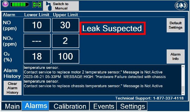
GENOSYL ®DS
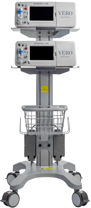
SECTION 11
SYSTEM MAINTENANCEThis section describes the process for performing high and low calibration for NO, NO 2,and O 2. Calibration of the GENOSYL DS should be performed every 28 days to ensure the accuracy of NO, NO 2, and O 2measurements. All calibrations can be performed at any time the Console is powered on, including while actively dosing. Air calibrates the low range for the NO and NO 2sensors. The high range of the NO and NO 2sensors are calibrated by using calibration gas tanks. The software will notify the user when calibration is due.
The display within the "Calibration" tab provides the status and the calibration due date of the different types of sensors. Air calibration provides the time of the last calibration since the System automatically performs this calibration every 4 hours while actively dosing or every 24 hours while powered on. A green check under status indicates that sensor has successfully been executed within the calibration period. A red X under status indicates that the sensor has not successfully been executed within the calibration period.
During calibration, the display will provide measured readings from each sensor. Note, there are two redundant NO sensors which are used to verify and ensure accuracy of the dosage provided by the System. During calibration, the display will provide a real-time status of the test with colored boxes to the right of the displayed sensor output. A yellow box indicates that the sensor is being calibrated. A green box indicates that calibration was successful for that sensor. A red box indicates that calibration for that sensor failed.
WARNING - ONLY use the calibration gas pressure regulators supplied by the manufacturer. Pressure regulators not supplied by the manufacturer may damage the sensors and may lead to patient injury.
- ALWAYS verify the correct NIST traceable calibration gas is being used and confirm the expiration date of the calibration gas prior to performing calibration. The use of incorrect or expired gas may result in inaccurate sensor readings and can lead to patient injury.
- NEVER perform NO or NO 2calibration within the MR scanner room. Calibration equipment is a potential projectile hazard.
CAUTION - ALWAYS perform a full-scale calibration of the GENOSYL DS when prompted by the System prior to use.
- ALWAYS confirm the correct flow direction of the installed one-way check valve in the sampling tee to avoid over pressurization of the sample system and damage to the device.
DISPLAY ACTION Warnings, Cautions and Notes 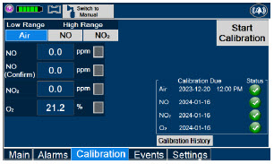
- Checkto make sure nothing is connected to the CAL port during Air Calibration.
- If the "Calibration" tab is not displayed, pressthe "Menu" tab to access the sub-level tabs.
- Pressthe "Calibration" tab on the display menu.
- Pressthe Low Range "Air" button.
- Pressthe blue "Start Calibration" button.
NOTE Air Calibration will take up to 2 minutes if not dosing, or 5 minutes if actively dosing. A progress bar is displayed in the lower left-hand corner of the display screen during the calibration process. 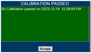
- Press"OK" to continue once calibration is complete.
NOTE If air calibration fails, ensure that nothing is connected to or blocking the CAL port. DISPLAY ACTION Warnings, Cautions and Notes 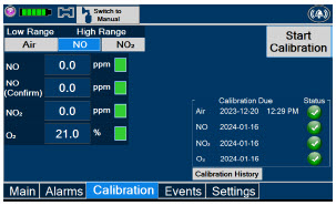
- If the "Calibration" tab is not displayed, pressthe "Menu" tab to access the sub-level tabs.
- Pressthe "Calibration" tab on the display menu.
- Pressthe High Range "NO" button.
- Pressthe gray "Start Calibration" button.
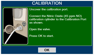
- Followthe onscreen instructions.
WARNING DO NOT open the valve prior to connecting to the CAL port. Opening the valve first will expose the user to NO gas.
DO NOT interrupt calibration until finished. If interrupted, the calibration will be cancelled.NOTE NO calibration takes approximately 2 minutes if not dosing, or 5 minutes if actively dosing. A progress bar is displayed in the lower left-hand corner of the display screen during the calibration process. 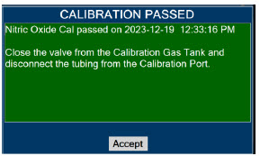
- Followthe onscreen instructions
- Press"Accept" to continue once calibration is complete.
WARNING DO NOT disconnect tubing from the calibration port prior to closing the valve. Disconnecting the tubing first will expose the user to NO gas. DISPLAY ACTION Warnings, Cautions and Notes 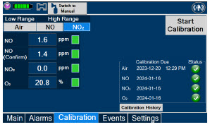
- If the "Calibration" tab is not displayed, pressthe "Menu" tab to access the sub-level tabs.
- Pressthe "Calibration" tab on the display menu.
- Pressthe High Range "NO 2" button.
- Pressthe gray "Start Calibration" button.
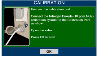
- Followthe onscreen instructions.
WARNING DO NOT open the valve prior to connecting to the CAL port. Opening the valve first will expose the user to NO 2gas.
DO NOT interrupt calibration until finished. If interrupted, the calibration will be cancelled.NOTE NO 2calibration takes approximately 2.5 minutes. A progress bar is displayed in the lower left-hand corner of the display screen during the calibration process. 
- Followthe onscreen instructions.
- Press"OK" once calibration is complete.
WARNING DO NOT disconnect tubing from the calibration port prior to closing the valve. Disconnecting the tubing first will expose the user to NO 2gas. The Console components require the following maintenance:
COMPONENT SCHEDULE Water Trap Per patient or as required (per Water Trap/ Sample Line Leak Test) GaussAlert™ Monthly functionality check Console Every 24 months or 10,000 pump hours, whichever is first The Console requires factory service every 24 months or 10,000 pump hours, whichever is first. The System will display an Information Message to remind the operator when service is required. Contact Technical Support at 877-337-4118for support or to schedule service.
11.3 Testing the GaussAlert™ Function
WARNING - Keep the test magnet tool away from pacemakers, ICDs, and other implanted medical devices.
- If either GaussAlert™ fails testing (does not alarm when the magnet tool is used), contact Technical Support at 877-337-4118to request a replacement.
- Do not use the GENOSYL DS in the MR Environment if neither GaussAlert™ is functional.
CAUTION - Do not use or store the test magnet tool in the MR scanner room.
- Keep the test magnet tool away from the GENOSYL DS user screen. Neodymium magnets can damage computer monitors, watches, pulse oximeters, and other mobile handheld devices.
- Keep the test magnet tool away from magnetic media such as credit cards, magnetic I.D. cards, cassette tapes, video tapes, or other such devices.
NOTE If the LED stay illuminated for longer than a brief flash, or does not illuminate at all, the battery needs to be replaced. Contact Technical Support at 877-337-4118to request a replacement. To use the GaussAlert™ test magnet tool to test alarm function, follow the steps listed below.
- Place the test magnet tool on the GaussAlert™ alarm bracket in the area identified in Figure 36.
- The alarm will activate and a short flash (less than two seconds) of the LED indicates proper function.
- Move the test magnet tool away from the GaussAlert™ until the alarm stops sounding.
- Repeat this procedure on the second GaussAlert™.
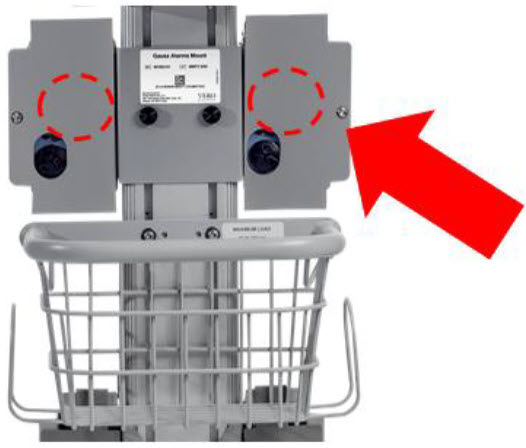
The following section will describe the emptying of the Water Trap. The Water Trap should be emptied when the liquid contents reach the horizontal black line marked on the Water Trap.
Prior to emptying the Water Trap, ensure the Gas Sample Line is removed and reattached after emptying the Water Trap.
11.4.1 Emptying the Water Trap
WARNING ALWAYS empty Water Trap before each use, when prompted by the System, and when the trap is more than half full. Allowing the Water Trap to completely fill will occlude the Sample Line which will interrupt patient gas NO, NO 2, and O 2concentration monitoring. Failure to monitor the patient gas NO, NO 2, and O 2concentrations may result in patient injury. DISPLAY ACTION 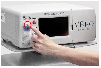
- RemoveWater Trap from Console by lifting latch and pulling the base of the Water Trap away from the Console.
- Removethe lid by pulling the lid from the base.
- Emptythe liquid contents.
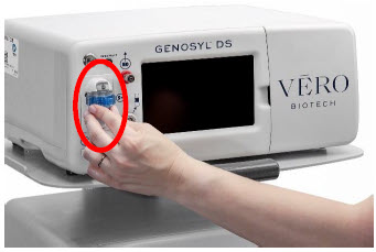
- Reattachthe lid by pushing it back onto base.
- Slidethe Water Trap back on the Console until it clicks into place.
If the Water Trap / Sample Line Leak Test fails, and Sample Gas Line integrity is confirmed with blue stopcock in place, replace the Water Trap.
WARNING - ALWAYS use a Water Trap supplied by the manufacturer. Using an incorrect water trap could result in non-functioning or inaccurate sensor readings.
- ALWAYS conduct Water Trap/ Sample Line Leak Test every time you empty or replace the Water Trap, as failure to do so may lead to an incorrect NO reading, which can result in injury or death.
DISPLAY ACTION 
- Removeold Water Trap from Console by lifting the latch and pulling the base of the Water Trap away from the Console.
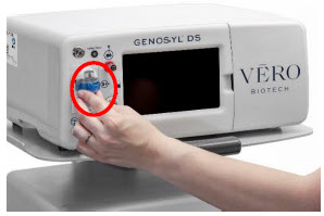
- Slidenew Water Trap back on the Console until it clicks into place. Replace sample line to Water Trap.
- Discardthe old Water Trap.
The battery will be serviced during scheduled maintenance performed by the manufacturer. If the need arises to replace the battery sooner than scheduled contact Technical Support at 877-337-4118to schedule a maintenance appointment. Battery is expected to last up to four hours under optimal conditions. Console will alarm when less than 15 minutes of battery life remains. See Section 10.3if you receive a Battery Error.
During storage, the GENOSYL DS may be stored with the power off, but the external power supply should be connected at least once every 3 months to ensure a minimum charge is maintained on the internal battery (see Section 13.6for additional information).
WARNING ONLY properly trained personnel should replace the battery. Incorrectly replacing the battery may result in a hazard such as excessive temperatures, fire, or explosion. 11.6.1 Enclosure, Connections, and Surfaces Other Than the Display
Prior to performing any cleaning or maintenance operations ensure that the GENOSYL DS Console has been completely powered down as specified in Section 6.1and that the AC/DC power supply external to the GENOSYL DS Console has been unplugged. Apply any mild detergent to cloth prior to wiping the System. Gently clean the outer surface of the Console, Cart, and Adaptive Sensor Cable with a soft damp cloth and mild detergent or isopropyl alcohol (70%).
CAUTION - DO NOT sterilize (e.g., autoclave, gas sterilize) any of the components of the System, as this may compromise performance.
- DO NOT use harsh cleaning agents ( seeTable 11) on the GENOSYL DS. Doing so may impair the structural integrity and/or function of the device.
- ONLY use a damp cloth to clean the Console and limit use of liquids around Console. Excess water can permanently damage the device.
- ALWAYS ensure the System is completely dry after cleaning before powering it ON. Failure to do so could result in equipment damage.
WARNING - NEVER submerge the GENOSYL DS, Cassette, or non-disposable Adaptive Sensor Cable. Submerging in liquid will damage the System and could cause electrical shorts which may result in injury or death.
- DO NOT clean the GENOSYL DS with the power connected and the System turned ON, as this may lead to injury (e.g., shock). Unplug AC/DC power supply external to the System prior to cleaning.
Table 11: Recommended Cleaning Agents CLEANING AGENT ACTIVE INGREDIENTS Avert by Diversey Sodium hypochlorite 1.312%
Other ingredients 98.688%Oxivir by Diversey Hydrogen Peroxide 0.5%
Other ingredients 99.5%CaviWipesXL by Metrex Disobutylphenoxyethxyethyl dimethyl benzyl ammonium chloride 0.28%
Isopropanol 17.20%
Inert ingredients 82.52%Sani-Cloth AF3 by PDI Healthcare n -Alkyl dimethyl ethybenzyl ammonium chlorides 0.14%
n-Alkyl dimethyl benzyl ammonium chlorides 0.14%
Other ingredients 99.72%Super Sani-cloth by PDI Healthcare n -Alkyl dimethyl ethybenzyl ammonium chlorides 0.25%
n-Alkyl dimethyl benzyl ammonium chlorides 0.25%
Isopropyl Alcohol 55.00%
Other ingredients 44.50%Turn off Console and disconnect from AC power. Gently clean with a damp cloth.
CAUTION - DO NOT touch or rub the display screen with abrasive cleaning compounds or organic solvents, as they may scratch and damage the screen.
- DO NOT spray or pour liquids directly on the controller or the display, as they may damage the screen.
11.6.3 Cleaning the Gauss Alarms Mount
Use a soft cloth dampened with water to clean the enclosure. Use an aqueous solution of up to 75% isopropyl alcohol for more efficient cleaning. Disinfection may be accomplished with the use of denatured alcohol.
The acceptable storage conditions for the Cart/Console are shown in the following table.
Temperature -20⁰ C to 60⁰ C Cart / Console Storage Humidity 15% to 95%, non-condensing Pressure 57 kPa to 110 kPa During storage, the GENOSYL DS may be stored with the power off, but the external power supply should be connected at least once every 3 months to ensure a minimum charge is maintained on the internal battery (see Section 13.6for additional information).
WARNING - MAKE SURE the GENOSYL DS is connected to AC wall power to charge the battery a minimum of once every 3 months to maintain a minimum battery charge. Failure to recharge the Console battery for extended timeframes may result in full discharge of the battery. If a Battery Error message occurs during startup of the System, contact Technical Support at 877-337-4118for assistance.
- ONLY properly trained personnel should replace the battery. Incorrectly replacing the battery may result in a hazard such as excessive temperatures, fire, or explosion.
- ONLY store the GENOSYL DS as outlined in the storage instructions. Not storing the device in alignment with its storage instructions can cause the device to be unsafe and lead to injury or death.
11.7.2 Cassette / Accessory Storage
GENOSYL DS may not function correctly if the Cassette or any of the System Accessories have been exposed to high levels of heat or humidity. Cassettes are supplied in a plastic container and should remain unopened until use. Cassettes should be stored at 25°C (77°F) with excursions permitted between 15°C to 30°C (59°F to 86°F). (See USP Controlled Room Temperature).
GENOSYL ®DS
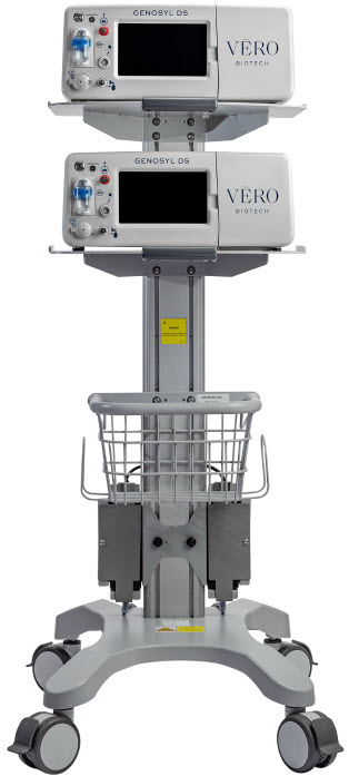
SECTION 12
MECHANICAL VENTILATIONWARNING - ONLY mechanical ventilators validated with the GENOSYL DS should be used. Not using a validated ventilator system can result in injury or harm.
- DO NOT use the GENOSYL DS with circle anesthesia ventilator systems. The GENOSYL DS has not been characterized or qualified for use with anesthesia breathing systems with recirculation of gases.
There are two main effects of connecting the GENOSYL DS to a ventilator breathing circuit:
- The System injects up to 0.9 LPM of NO/air (21% Oxygen) into the inspiratory output of the ventilator.
- The System samples up to 0.3LPM from the ventilator circuit as a measurement to the built-in gas analyzers
The results of adding and subtracting gas into the ventilator circuit are described in sections 12.1.1 to 12.1.4:
The ventilator typically is flowing gas to the patient with enhanced oxygen content from room air, ranging from 21% at 100% oxygen. The DS is injecting NO mixed with air with a concentration of oxygen at nominally 21%. Thus, except for the case where the ventilator is supplying gas to the patient at 21% oxygen, there is some dilution of the oxygen delivered to the patient.
This dilution may be determined with the following equation:
Percent O 2to Patient = [{%O 2/100 + (Flow inj/Flow vent)×0.21}/{1 + (Flow inj/Flow vent)}]×100
Where:
- Flow inj= Injection flow in same units as ventilator flow
- Flow vent= Ventilator flow in same units as injection flow
- %O 2= Percent oxygen out of ventilator
- 0.21 = Fraction of oxygen in injection flow (21%)
Table 12below shows the maximal dilution effect on the concentration of oxygen supplied to the patient for set ventilator flow settings with NO doses ≤40 ppm and a nominal flow from the GENOSYL DS of 0.6 LPM of NO/air (21% oxygen) into the inspiratory output of the ventilator. Actual dilution may vary based on respiratory device settings and clinical scenarios.
This is applicable for all compatible gas delivery systems, unless otherwise noted below.
NOTE The following respiratory devices demonstrated oxygen dilution that is representative of in ection flow greater than 0.6LPM in testing with NO doses ≤ 40 ppm. Use the calculation above to estimate maximal dilution using Flowinj = 0.64 LPM: - Bio-Med Devices MVP-10
Table 12: Oxygen Dilution Oxygen (%) Supplied from Ventilator 100 80 60 40 21 Ventilator Flow
(LPM)Oxygen (%) Delivered to Patient 70 99 79 60 40 21 20 98 78 59 39 21 15 97 78 59 39 21 10 96 77 58 39 21 9 95 76 58 39 21 8 94 76 57 39 21 7 94 75 57 39 21 6 93 75 56 38 21 5 92 74 56 38 21 4 90 72 55 38 21 3 87 70 54 37 21 2 82 66 51 36 21 1 70 58 45 33 21 0.5 57 48 39 30 21 Higher injection flows may be employed by the GENOSYL DS when administering NO doses >40 ppm. Use injection flow of 0.9 LPM to estimate the maximal dilution effect on the concentration of oxygen supplied to the patient when administering NO doses >40 ppm.
When using volume ventilation with the GENOSYL DS, the tidal volume delivered to the patient may show small changes due to the addition and subtraction of gases by the Delivery System. Some minor ventilator adjustments to the minute volume may be required. Maximum total flow added to the ventilator circuit is 0.9 LPM of concentrated NO gas and the maximum total flow removed from the ventilator circuit is 0.3 LPM of sampled gas.
The addition and subtraction of gases by the GENOSYL DS may affect the trigger sensitivity of the ventilator when using synchronized modes of ventilation. This may cause ventilators which have flow trigger modes to auto-cycle or result in apnea alarms, especially where the trigger flow is less than the total flow added.
The maximum combination of dose (ppm) and flow (LPM) is 800 ppm × LPM (e.g., 20 ppm with 40 LPM, 40 ppm at 20 LPM, etc.). The System is capable of delivering NO at a minimum of 1 ppm × LPM (e.g., 1 ppm at 1 LPM). See the graph below for the minimum and maximum dose ranges for the System, based on ventilator circuit total minute volume.
The GENOSYL DS has a safety fallback where the delivery of nitric oxide will be interrupted when a sampled value higher than 3 ppm NO 2is detected. Once sample value of NO 2is below 3.0 ppm, the Console will auto resume delivery of NO at set dose. The table below outlines the dose at which a delivery interruption was observed during validation testing in a laboratory setting due to high NO 2. For validation testing, FiO 2was set at 100% and the maximum bias flow setting for each ventilation device was used. If there is an unexpected change in NO 2concentration, the delivery system should be assessed in accordance with the recommended actions for troubleshooting Section 10.8, and the NO 2analyzer should be recalibrated. The dose of GENOSYL and/or FiO 2should be adjusted as appropriate.
CAUTION - When using spontaneousbreathing modes on respiratory device, NO 2levels may exceed 3.0 ppm when dosing ≥ 57 ppm NO into 100% FiO 2and maximum bias flow, resulting in nitric oxide delivery interruption. Once sample value of NO 2is below 3.0 ppm, the Console will auto resume delivery of NO at set dose. Refer to Section 12.1.5 Table 13for additional information.
- When using non-spontaneousbreathing modes on respiratory device, NO 2levels may exceed 3.0 ppm when dosing ≥ 63 ppm NO into 100% FiO 2and maximum bias flow, resulting in nitric oxide delivery interruption. Once sample value of NO 2is below 3.0 ppm, the Console will auto resume delivery of NO at set dose. Refer to Section 12.1.5 Table 13for additional information.
Table 13: NO Dose at which NO 2exceeded 3ppm NO 2Threshold when dosing at 100% FiO 2and Maximum bias flow Manufacturer Model Set NO dose at which NO 2exceeded 3 ppm threshold in spontaneous modes Set NO dose at which NO 2exceeded 3 ppm threshold in nonspontaneous modes Bio-Med Devices Crossvent 2+ 64 82 Bio-Med Devices MVP-10 75 70 Drӓger V500, VN 500, V600, VN 600, V800, VN 800 69 72 Hamilton C1/MR1/T1 72 70 Hamilton C6 72 67 Hamilton G5 72 N/A Puritan Bennett 980 59 64 Vyaire Medical Inc. AVEA 74 82 Fisher & Paykel Optiflow JR 2 57 N/A Fisher & Paykel Optiflow 69 N/A 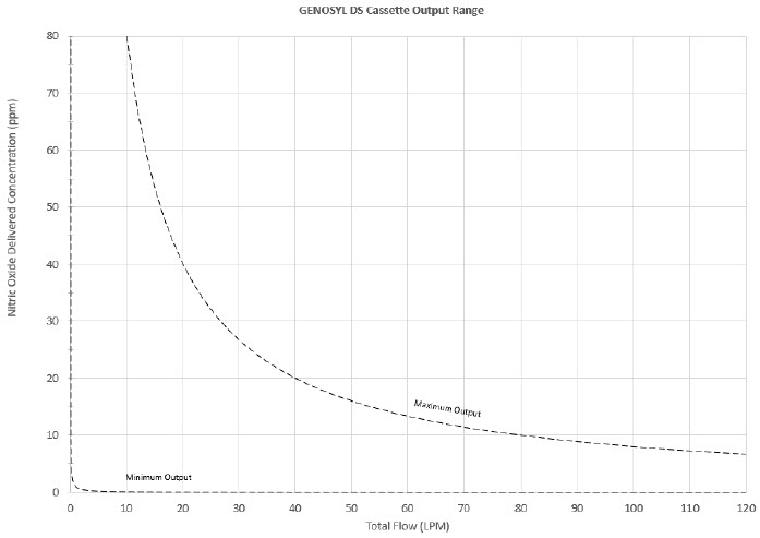
VERO Biotech performs validation testing which determines the compatibility of ventilator/gas delivery systems with the GENOSYL DS. During this compatibility testing, the GENOSYL DS is evaluated for the following parameters while connected to each ventilator/gas delivery system:
- NO Dose Accuracy:Continuous and accurate delivery of a targeted dose of nitric oxide within ± 20% of setpoint or within ± 2 ppm, whichever is greater.
- Respiratory Device Breath Delivery and Alarms:The respiratory device breath delivery and alarms continue to function as intended by the manufacturer across the range of operating conditions.
- NO 2Performance: NO 2remains within acceptable limits less than 1.0 ppm with 60% FiO 2and ≤40 ppm NO.
- O 2Dilution: Post dilution O 2level delivery is maintained within acceptable limits and conforms with the information presented in the GENOSYL DS Operator's Manual, Section 12.1.1, "Oxygen Dilution".
- NO Concentration Transients:NO concentration transients are ≤150% of mean concentration and as low as 0.0 ppm as long as the transient duration does not exceed 10% of the volumetric duration of the breath.
The testing performed demonstrated conformance with all specified requirements. The following ventilators and non-invasive gas delivery systems in Table 14have been validated for use with the GENOSYL DS. See Section 3.2for use configurations.
WARNING - ALWAYS use the GENOSYL DS in accordance with the indications, usage, contraindications, warnings, and precautions described in the GENOSYL prescribing information and labeling. Refer to latest approved prescribing information and labeling prior to use.
- The approved patient population for the GENOSYL DS as specified in the drug labeling for GENOSYL (nitric oxide) for inhalation, is limited to neonates. The GENOSYL DS is not intended to be used in other patient populations.
Table 14: Details of Validated Systems
Validated ventilators were not tested with a nebulizer.
Use of a Mixer is recommended when delivering in specific tidal volume ranges on various ventilation devices. Refer to Table 15for when a Mixer is and is not recommended.
Manufacturer Models Hospital External Transport Anesthesia Gas Machine Modes Validated Bio-Med Devices Crossvent 2+ Cycle
CPAPBio-Med Devices MVP-10 Cycle
CPAPDräger Fabius GS, Fabius GS Premium, Fabius Tiro VC
PC
PS
SIMV/PSDräger V500, VN 500, V600, VN 600, V800, VN800 VC-AC
VC-SIMV
VC-CMV
PC-AC
PC-SIMV
PC-CMV
PC-BIPAP
VC-MMV
PC-APRV
PC-PSV
SPN-CPAP/PS
SPN-CPAP/VS
SPN-PPSGE Aisys CS2 VCV
PCV
PCV-VG
PSVPro
CPAP+PSV
SIMV PCV
SIMV VCV
SIMV PCV-VG
ManualHamilton C1/MR1 PCV+
PSIMV+
APVcmv
APVsimv/SIMV+
ASV
DuoPAP
APRV
SPONT
NIV
NIV ST
nCPAPA
nCPAP PCHamilton C6 APVcmv
APVsimv
PCV+
PSIMV+
DuoPAP
APRV
SPONT
ASV
NIV
NIV-ST
nCPAP-PSHamilton G5 (S)CMV
P-CMV
P-SIMV
APVcmv
APVsimv
ASV
DuoPAP
APRV
SPONT
VS
NIV
NIV-ST
nCPAP-PS
SIMVHamilton T1 PCV+
PSIMV+
APVcmv
APVsimv/SIMV+
ASV
DuoPAP
APRV
SPONT
NIV
NIV ST
nCPAP
nCPAP PCPuritan Bennett 980 A/C PC
A/C VC
A/C VC+
NIV AC PC
NIV AC VC
BiLevel
BiLevel PC PS
BiLevel PC TC
NIV CPAP
SPONT VS
NIV SPONT PS
SPONT TC
SPONT PAV+Vyaire Medical Inc. AVEA Volume A/C
Pressure A/C
Volume SIMV
Pressure SIMV
CPAP/PSV
PRVC A/C
PRVC SIMV
APRV/BiPhasic
TCPL A/C
TCPL SIMV
Nasal CPAP/IMVFisher & Paykel Optiflow JR 2 N/A Fisher & Paykel Optiflow N/A Table 15: Validated Compatibility with and without Inline Mixer
At the lowest tested rate of 6 BPM, a Mixer may be used to reduce intra-breath dose variability as outlined in Table 15 below. Intra-breath dose variability was not observed at a respiratory rate of 60 BPM.
For mixer recommendations when using an anesthesia gas machine, refer to Table 6.
See Section 3.4for assembly instructions for Injection Assembly with Adaptive Sensor and Mixer Assembly with Adaptive Sensor.
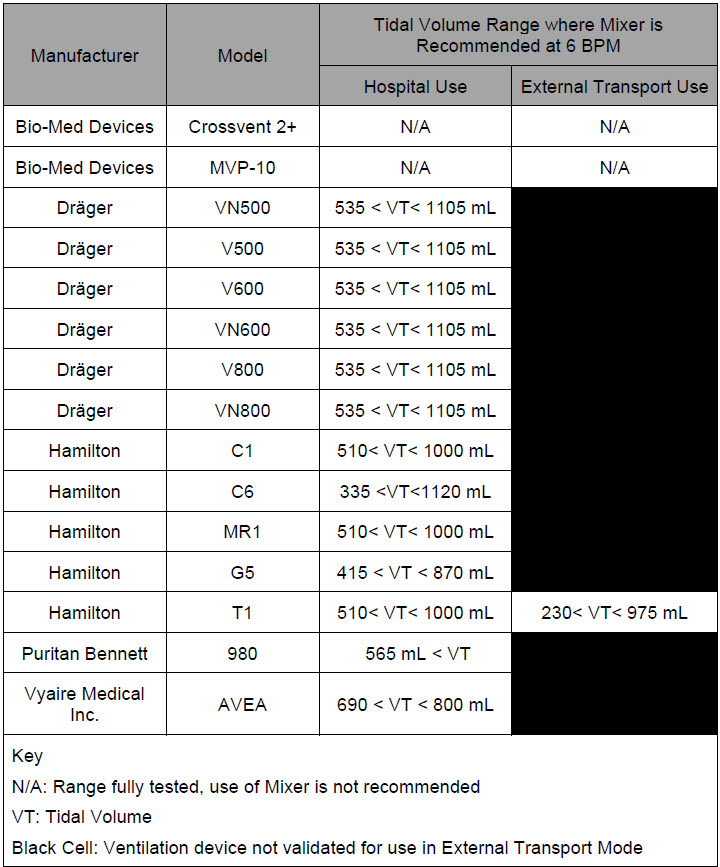
GENOSYL ®DS

SECTION 13
PRODUCT SPECIFICATIONSNO DOSING Accuracy ± 20% or ± 2 ppm (whichever is greater) Range 0 to 80 ppm Flow rate (max) 900 mL/min GAS SENSOR Range Resolution Accuracy NO 0 - 10 ppm 0.1 ppm ≤20 ppm: ± (20% of actual concentration + 0.5)
>20 ppm:± (10% of actual concentration + 0.5)10 – 100 ppm 1 ppm NO 2 0.0 - 12 ppm 0.1 ppm ± 20% of actual concentration, or ± 0.5 ppm, whichever is greater O 2 18 - 100% 1% ± volume fraction of 2.5% +2.5% of gas level - Class I equipment
- Ordinary Equipment IPX1
- Continuous Use
- Essential Performance: The System shall continue to deliver a controlled dose, as configured by the user (e.g., 20 ppm @ 6 LPM within +/- 20%) with NO 2< 3 ppm and O 2= 21 ±3% in room air for the specified range of use conditions.
- ANSI ES 60601-1
- IEC 60601-1-2
- IEC 60601-1-8
NOTE Disconnect main power cord from the wall outlet to isolate equipment from main power. Do not position equipment to make it difficult to disconnect equipment from main power. - Medical Grade Class I
- Input: 100-240 V, 50-60 Hz, 2A
- Output: 18 V DC, 8.3 A
- 150 Watts Max
- Fully charged Battery is expected to last up to four hours under optimal conditions. Console will alarm when less than 15 minutes of battery life remains. See Section 10.3if you receive a Battery Error.
- Typical battery life is 300 charge/discharge cycles.
- The battery will be serviced during scheduled maintenance performed by the manufacturer.
- If the need arises to replace or dispose of the battery sooner than scheduled contact Technical Support to schedule a maintenance appointment.
The battery has an embedded 5 segment LCD battery indicator viewable through side panel window. The segments will display the following information:
- 5 segments filled – 81%-100% charged
- 4 segments filled – 61%-80% charged
- 3 segments filled – 41%-60% charged
- 2 segments filled – 21%-50% charged
- 1 segment filled – 1% - 20% charged
- No battery indication – below 1%
- Most significant segment flashing – charging
- Most significant segment not flashing – not charging
13.6.1 Battery Charge Status Indicator
COLOR ERROR Solid Red Battery Power Supply Error Blinking Red Communication Failure or Hardware Error Solid Amber Console is unplugged and using battery power Blinking Amber Console is running and running on low battery Solid Green Console is plugged in and battery is fully charged Blinking Green Console is plugged in and the battery is charging - Touch screen – Resistive
- Brightness – 400 cd/m 2
- Resolution – 800 × 480 pixels, color
CART Weight 18.15 kg (40.01lbs) Width × Length 47.8 cm (18.8 in) × 66.7 cm (26.3 in) Height 120.7 cm
(47.5 in)CONSOLE Weight 8.85 kg (19.75 lb) Width × Length 40.6 cm × 30.5 cm (16 in × 12 in) Height 17 cm (6.75 in) CASSETTE Weight 0.42 kg (0.93 lb) Width × Length 11.4 × 3.8 cm (4.5 in × 1.5 in) Height 13 cm (5.1in) ENVIRONMENTAL RANGES Operating Temperature 5⁰ C to 40⁰ C Humidity 15% to 95%, non-condensing Pressure 57 kPa to 110 kPa Altitude Under 15,000 feet Storage Temperature -20⁰ C to 60⁰ C Humidity 15% to 95%, non-condensing Pressure 57 kPa to 110 kPa Altitude Under 15,000 feet Water Ingress Protection IPX1 13.10 GaussAlert™ Specifications
Standard Factory Preset Alarm Thresholds 100 Gauss (10 mT) Audio Alarm Typical Sound Pressure 92dB (A) at 24 inches Audio Alarm Frequency 2900 Hz +/- 250Hz Typical Battery Life 5 years Sensor Type Mechanical with panoramic uniform sensitivity 13.11 MR Signal-to-Noise Ratio and Artifact Dimension Analysis
MR image artifact was evaluated using 1.5 T and 3 T MRI Systems. Testing was conducted using standard American College of Radiology (ACR) sequences and a standard ACR large phantom placed inside a transmit-receive head coil. Duplicate sequences were performed to acquire the same images with and without the GENOSYL DS operating on battery power inside the MRI suite.
The GENOSYL DS compatibility test results are as follows:
Artifact Dimensional Analysis 1.5 T The maximum dimensional change in images acquired during the operation of the GENOSYL DS was < 1 mm. 3 T The maximum dimensional change in images acquired during the operation of the GENOSYL DS was < 1 mm. Image Quality Signal-to-Noise Ratio Analysis 1.5 T The average SNR change was -35%. The average SFNR change was -42%. The PIU values were all 96%. 3 T The average SNR change was -25%. The average SFNR change was -22%. The PIU values were all greater than 94%. The GENOSYL DS does not distort the geometric accuracy and the image intensity uniformity is not adversely affected by the presence of the GENOSYL DS at the 100 Gauss line. The SNR and SFNR are both impacted by the presence of the GENOSYL DS, to a more pronounced degree when the equipment is powered via a wall outlet inside the MRI suite versus operating on the battery.
NOTE - The test results presented here were obtained with the GENOSYL DS operating on battery power.
- If using the GENOSYL DS while connected to wall power, it is recommended to route the power cords through a waveguide.
Emissions test Compliance Electromagnetic Environment – Guidance RF emissions
CISPR 11Group 1 The GENOSYL DS uses RF energy only for its internal function. Therefore, its RF emissions are very low and are not likely to cause any interference in nearby electronic equipment. Class B The GENOSYL DS is suitable for use in all establishments, including domestic establishments and those directly connected to the public low voltage power supply network that supplies buildings used for domestic purposes. RF conducted emissions per CISPR 11 Ed. 5.1b:2010 Class B The GENOSYL DS is suitable for use in all establishments, including domestic establishments and those directly connected to the public low voltage power supply network that supplies buildings used for domestic purposes. Harmonic emissions IEC 61000-3-2 Class A Voltage fluctuations/flicker emissions
IEC 61000-3-3Complies Guidance and Manufacturer's Declaration – Electromagnetic Immunity The GENOSYL DS is intended for use in the electromagnetic environment specified below. The customer or the user of the GENOSYL DS should assure that it is used in such an environment Immunity Test IEC 60601 Test Level Compliance Level Electromagnetic Environment - Guidance - * The ISM (industrial, scientific and medical) bands between 150 kHz and 80 MHz are 6.765 MHz to 6.795 MHz; 13.553 MHz to 13.567 MHz; 26.957 MHz to 27.283 MHz; and 40.66 MHz to 40.70 MHz.
- † The compliance levels in the ISM frequency bands between 150 kHz and 80 MHz and in the frequency range 80 MHz to 2.7 GHz are intended to decrease the likelihood that a portable communications device could cause interference if it is inadvertently brought into patient areas. For this reason, an additional factor of 10/3 is used in calculating the recommended separation distance for transmitters in these frequency ranges.
- ‡ Field strengths from fixed transmitters, such as base stations for radio (cellular cordless) telephones and land mobile radios, amateur radio, AM and F M radio broadcast and TV broadcast cannot be predicted theoretically with accuracy. To assess the electromagnetic environment due to fixed R transmitters, an electromagnetic site survey should be considered. If the measured field strength in the location in which the GENOSYL DS is used exceeds the applicable RF compliance level above, the GENOSYL DS should be observed to verify normal operation. If abnormal performance is observed, additional measures may be necessary, such as reorienting or relocating the GENOSYL DS.
- § Over the frequency range 150 kHz to 80MHz, field strengths should be less than 3 V/m.
Electrostatic discharge (ESD)
IEC 61000-4-2±8 kV contact
±15 kV air±8 kV contact
±15 kV airThe relative humidity should be at least 5%. Electrical fast transient/burst
IEC 61000-4-4±2 kV for power supply lines ±2 kV for power supply lines Mains power quality should be that of a typical commercial or hospital environment. Surge
IEC 61000-4-5AC line: Line to Line ±0.5kV, ±1 kV & Line to GND ±0.5kV, ±1 kV, ±2kV AC line: Line to Line ±0.5kV, ±1 kV & Line to GND ±0.5kV, ±1 kV, ±2kV Mains power quality should be that of a typical commercial or hospital environment. Voltage dips, short interruptions and voltage variations on power supply input lines
IEC 61000-4-110% during 0.5 cycle 0% (100% reduction) for 1 cycles 70% (30% reduction) for 25 cycles
0% for 250 cycles- Short interruptions0% during 0.5 cycle 0% (100% reduction) for 1 cycles 70% (30% reduction) for 25 cycles
0% for 250 cycles- Short interruptionsMains power should be that of a typical commercial or hospital environment. If the user of the GENOSYL DS requires continued operation during power mains interruptions, it is recommended that the GENOSYL DS be powered from an uninterruptible power supply or a battery. Power frequency
(50/60 Hz)
Magnetic field
IEC 61000-4-830 A/m 30 A/m with dwell time of 60sec Power frequency magnetic fields should be at levels characteristic of a typical location in a typical commercial or hospital environment. NOTE: U Tis the AC main voltage prior to application of the test level. Conducted RF
IEC 61000-4-66 V rms 150 kHz to 80 MHz in ISM bands * 10 V 80% AM @ 1 kHz
150 kHz - 80 MHz in ISM bands,Except as indicated on page 10-137, portable and mobile RF communications equipment, including cables, should be used no closer to any part of the GENOSYL DS than the recommended separation distance calculated from the equation applicable to the frequency of the transmitter. Recommended separation distance:
d=1.2√P
d=1.2√P
d=1.2√P 80 MHz to 800 MHz
d=2.3√P 800 MHz to 2.7 GHz
where P is the maximum output power rating of the transmitter in watts (W) according to the transmitter manufacturer and d is the recommended separation distance in meters (m). †Radiated RF
IEC 61000-4-310 V /m 80MHz to 2.7 GHz 10 V /m 80 MHz to 2.7 GHz Field strengths from fixed RF transmitters, as determined by an electromagnetic site survey, ‡should be less than the compliance level in each frequency range. §Interference may occur in the vicinity of equipment marked with the following symbol:

NOTE NOTE 1: At 80 MHz and 800 MHz, the higher frequency range applies.
NOTE 2: These guidelines may not apply in all situations. Electromagnetic propagation is affected by absorption and reflection from structures, objects and people.Recommended separation distances between portable and mobile RF communications equipment and the GENOSYL DS The GENOSYL DS is intended for use in an electromagnetic environment in which radiated RF disturbances are controlled. The customer or the user of the GENOSYL DS can help prevent electromagnetic interference by maintaining a minimum distance between portable and mobile RF communications equipment (transmitters) and the GENOSYL DS as recommended below, according to the maximum output power of the communications equipment except as indicated on page 10-166. Rated Maximum Output Power of Transmitter W Separation Distance According to Frequency of Transmitter, m 150 kHz to 80 MHz
d=1.2√P80 MHz to 800 MHz
d=1.2√P800 MHz 2.5 GHz
d=2.3√P0.01 0.12 0.12 0.23 0.1 0.38 0.38 0.73 1 1.2 1.2 2.3 10 3.8 3.8 7.3 100 12 12 23 For transmitters rated at a maximum output not listed above, the recommended separation distance d in meters (m) can be estimated using the equation applicable to the frequency of the transmitter, where P is the maximum output power rating of the transmitter in Watts (W) according to the transmitter manufacturer. Immunity Test Standards Tested Compliance Level Electromagnetic Environment - Guidance Radiated RF
AIM 7351731 - Medical Electrical Equipment and System Electromagnetic Immunity Test for Exposure to Radio Frequency Identification Readers- ISO 14223 (Annex A)
- ISO/IEC 14443-3 (Type A) (Annex B)
- ISO/IEC 14443-4 (Type B) (Annex C)
- ISO/IEC 15693 (ISO/IEC 18000-3 Mode 1) (Annex D)
- ISO/IEC 18000-7 (Annex E)
- ISO/IEC 18000-63 Type C (Annex F)
- ISO/IEC 18000-3 (Mode 3)
- ISO/IEC 18000-4 Mode 1 (Annex G)
Per the Annex in the standard System tested as compatible with RFID tags/communication Frequencies of portable and mobile transmitters for which the recommended separation distance is 30 cm (12 in).
Band
(MHz)Service 380 - 390 TETRA 400 430 - 470 GMRS 460, FRS 460 704 - 787 LTE Band 13, 17 800 - 960 GSM 800/900 TETRA 800, iDEN 820, CDMA 850, LTE Band 5 1,700 – 1,990 GSM 1800; CDMA 1900; GSM 1900; DECT; LTE Band 1, 3, 4, 25; UMTS 2,400 – 2,570 Bluetooth, WLAN, 802.11 b/g/n, RFID 2450, LTE Band 7 5,100 – 5,800 WLAN 802.11 a/n GENOSYL ®DS
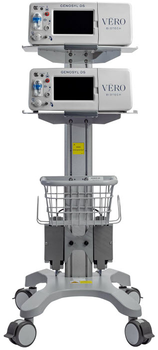
INDEX
KEY WORD INDEX Adjusting the dose 113 Adjustments, alarms, high and low levels for NO, NO2, and O2 185 Adjustments, date and time 59 Adjustments, dose in manual mode 56 Adjustments, dose in primary mode with keypad 62 Adjustments, ventilator for minute volume 234 Aerosol Delivery 95 Alarm, Battery Error 194 Alarm, Calibration Required 193 Alarm, Hardware Failure 193 Alarm, Line Occlusion 195, 196 Alarm, Low NO 192 Alarms, Battery Not Detected 197 Alarms, Cassette Failure 200 Alarms, Cassette Not Operational 198 Alarms, Cassette Time Remaining 201 Alarms, Configuration Parameters Incorrect 197 Alarms, Delivery Flow Error 202 Alarms, Gauss alarm 207 Alarms, High NO2/NO shutdown 190 Alarms, High O2 201 Alarms, Low Battery 200 Alarms, Low O2 201 Alarms, Service Due Date Expired 201 Alarms, Service Due Date Within 2 Days 205 Alarms, Service Required 194, 198 Alarms, System Running on Battery Only 204 Alarms, Water Trap Not Detected 196 ANESTHESIA GAS MACHINES 174 Bagging 116 Bagging, manual ventilation 116 Bagging, manual ventilation circuit setup 74, 93 Battery, backup 33 Battery, error alarm 194 Battery, low battery alarm 200 Battery, not detected alarm 197 Buttons, operational, display screen 61 Calibration, Air 217 Calibration, auto air calibration required 198 Calibration, calibration due 206 Calibration, calibration due date 216 Calibration, calibration due in less than 3 days 205 Calibration, calibration failed message 198 Calibration, calibration required alarm 193 Calibration, explanation 216 Calibration, history 59 Calibration, NO 218 Calibration, NO2 220 Calibration, tab 58 Cart, storage 228 Cassette, activation 110 Cassette, cassette status on display screen 63 Cassette, damage 208 Cassette, description 49 Cassette, disposal 38, 128 Cassette, failure alarm (cassette not operational) 200 Cassette, indication of use 49 Cassette, indicator not blue 208 Cassette, insertion 101 Cassette, mechanical specifications 246 Cassette, output range 234 Cassette, removal 124, 167 Cassette, storage 228 Cassette, to expire alarm (time remaining) 201 Cassette, to expire message (time remaining) 206 Cassette, Water Trap / Sample Line Leak Test 68 Cautions 3, 178 Cautions, User Responsibility 32 Cleaning, console 226 Cleaning, display screen 227 Cleaning, GaussAlert 227 Components, use of non-specified components 74 Components, use outside of product labeling 9 Connections, console 86 Connections, example ventilator circuit setup 74 Connections, GENOSYL DS ventilator circuit 91 Connections, manual ventilation bag 93 Connections, Non-Invasive Gas Delivery Systems 79 Connections, power cord to console 100 Connections, Standard Ventilators 75 Connections, ventilator circuit 94 Console, backup battery 33 Console, cleaning 226 Console, connections 86, 87 Console, gas monitoring 37 Console, maintenance schedule 222 Console, mechanical specifications 246 Console, modes operation 56 Console, primary definition 19 Console, repair or replacement 32 Console, standby definition 19 Console, start up 100 Console, storage 228 Console, use as a backup 120 Console, user responsibility 32 Date, alarm history 186 Date, calibration due date 216 Date, calibration due date passed 206 Date, change date and time 59 Date, expiration 81 Date, manufacture 21 Date, service date within 2 days 205 Date, service due within 14 days 205 Date, service past due 201 Date, use by 23 Display, cleaning 227 Display, definition 19 Display, menu tab navigation 57 Display, screen 56 Display, screen cassette status 63 Display, screen operational buttons 61 Display, screen overview 56 Display, specifications 246 Dosing, during manual (bagging) ventilation 116, 164 Dosing, during use as a backup 120 Dosing, resuming primary dosing 119, 166 Dosing, system performance specifications 244 EMI/EMC, specifications 248 External Transport
Transport, External138 External Transport Cassette 142 Feedback loop, explanation 33 Fresh Gas Flow 176 Gas lines, detailed explanation 54 Gas monitoring 37 Gauss alarm 207 GaussAlert maintenance 222, 223 GaussAlert specification 247 GaussAlert, cleaning 227 GaussAlert, testing 223 Height, cart specifications 246 Height, cassette specifications 246 Humidity, operating humidity 247 Humidity, storage/transport 247 Indications for Use 33 Injection Assembly 83 Injection Assembly, assembly 83, 149 Label, expiration date 81 Labeling, intended population for use 33 Labeling, use outside of 9 Labeling, user responsibility 32 Lable, gas lines 54 Maintenance, GaussAlert 222 Manual ventilation 116, 164 Manual Ventilation Line, detailed explanation 54 Manual Ventilation Line, function 51 Manual Ventilation Line, manual vent bag connection 93 Messages, informational, Auto Air Calibration Required 198 Messages, informational, Calibration Due 206 Messages, informational, Cassette Will Expire in 2 Hours 206 Messages, informational, Incomplete Calibration 198 Messages, informational, Service Due Date within 14 Days 205 Mixer, assembly 84 Mixer, definition 20 Mixer, Function 52 Mixer, principles of operation 37 Modes of Operation, console 56 Monitoring, gas 33, 37 Monitoring, gas sensor 37 Monitoring, NO, NO2 and O2 concentrations and water trap 82 Monitoring, patient 7 Mount, transport 140 MR exclusion zone 133 MR Image Artifact 247 MR Scanner Room 133 MR Signal to Noise Ratio 247 Nebulizers 95 NO Injection Line, detailed explanation 54 NO Injection Line, Function 51 NO Injection Line, NO port connection 94 Notes 3, 174, 178 Notes, user responsibility 32 PARTS / COMPONENTS, GENOSYL DS 23 Pneumatic Nebulizers 10, 95 Power connection to console 100 Power, battery specifications 245 Power, black rocker switch powering on 101 Power, cord 100 Power, EMI/EMC 249 Power, EMI/EMC specifications 249 Power, power down before cleaning 226 Power, power supply 245, 248 Power, power supply specifications 245 Power, screen does not turn on 208 Power, silver power button, powering on 101 Power, system does not shutdown 208 Pressure, operating pressure 247 Pressure, storage/transport 247 Problems, see Troubleshooting 208 Procedure, adjusting the dose 113 Procedure, air calibration 217 Procedure, cart/console storage 228 procedure, cassette activation 110 Procedure, cassette disposal 128 Procedure, cassette insertion 101, 155 Procedure, cassette/accessory storage 228 Procedure, cleaning 226 Procedure, console connections 86 Procedure, console shutdown 124, 167 Procedure, console startup 100 Procedure, console use as a backup 120 Procedure, emptying the water trap 224 Procedure, gas lines connections 86 Procedure, GENOSYL DS ventilator circuit connections 91 Procedure, injection assembly assembly 83, 149, 152 Procedure, manual ventilator bag connector 93 Procedure, mechanical ventilator circuit connections 91 Procedure, mixer assembly 84 Procedure, NO Calibration 218 Procedure, NO2 calibration 220 Procedure, resuming primary dosing after manual mode 119, 166 Procedure, ventilatory circuit assembly pre-check 81 Procedure, water trap replacement 225 Procedure, weaning 113 Pumps, general information 33 Pumps, louder than normal 208 Pumps, NO delivery into the ventilator system 33 Pumps, noise level 208 Removal, cassette prior to shutdown 124, 167 Removal, water trap from console to empty 224 Removal, water trap from console to replace 225 Responsibility, User 32 Sample Line Filter Connection 89 Sample Line Leak test 68 Sample Line, detailed explanation 54 Sample Line, function 51 Sample Line, leak test 105, 158 Sample Line, sample tee connection 95, 149, 152, 179 Sample Line, water trap connection 86 Sensors, calibration 216 Sensors, principles of operation 37 Service, battery replacement 245 Service, due date within 14 days 205 Service, due date within 2 days 205 Service, repair of replacement 32 Service, scheduling 222 Service, service required alarm 194, 198 Service, yearly 222 Shutdown
Cassette Status Indicators69 Specification, GaussAlert 247 Specifications, transport mount 143 Storage, cart and console 228 Storage, cassette 228 Temperature, operating temperature 247 Temperature, storage/transport 247 Transport equipment weight 143 Transport Mount 144 Transport mount specifications 143 Transport, environmental 247 Transport, environmental specifications 247 Ventilator Compatibility 236 Ventilator, circuit assembly pre-check 81 Ventilator, minute volume 234 Ventilator, oxygen dilution 232 Warning, user responsibility 32 Warnings 3, 68, 124, 167 Water Trap Leak Test 68 Water trap, emptying 224 Water Trap, maintainance schedule 222 Water Trap, replacing 225 Weaning 113 Weight, cart specifications 246 Weight, cassette specifications 246 Weight, console specifications 246 Weight, transport equipment 143 Width and Length, cart specifications 246 Width and Length, cassette specifications 246 Width and Length, console specifications 246 VERO Biotech and GENOSYL are registered trademarks of VERO Biotech Inc.
© 2025 VERO Biotech. Printed in U.S.A. LBL-602502 Rev I JUNE 2025
Please read full prescribing information enclosed.
877.337.4118 | VERO-biotech.com
- 1 NIOSH Pocket Guide to Chemical Hazards, Dept of Health & Human Services, Centers for Disease Control and Prevention, National Inst for Occupational Safety & Health. Publication 2005-149, Sept 2007.
- 2 Hess et al, Use of Inhaled Nitric Oxide in patients with Acute Respiratory Distress Syndrome. Respiratory Care 1996; 41(5):424-446.
- 3 Phillips M, Hall TA, Sekar K, Tomey JL. Assessment of Medical Personnel Exposure to Nitrogen Oxides During Inhaled Nitric Oxide Treatment of neonatal and Pediatric Patients. Pediatrics. 1999;104(5):1095-1110.
- 4 Qureshi MA, Shah NJ, Hemmen CW, Thill MC, Kruse JA.Exposure of Intensive Care Nurses to Nitric Oxide and Nitrogen Dioxide during Therapeutic use of Inhaled Nitric Oxide in Adults with Acute Respiratory Distress Syndrome. Am. J. Crit Care, 2003;12(2):147-153.
-
INSTRUCTIONS FOR USE
VĒRO
BIOTECHGENOSYL ®
DELIVERY SYSTEM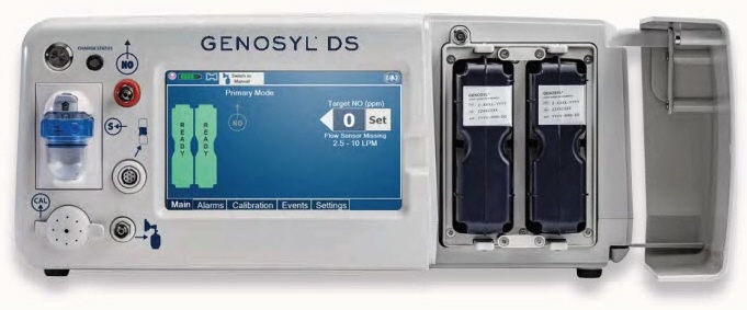
FOR DELIVERY OF
GENOSYL ®
(NITRIC OXIDE)
GAS FOR INHALATIONQUICK REFERENCE GUIDE
Technical Support: 877.337.4118
GENOSYL ®DS QUICK REFERENCE GUIDE TABLE OF CONTENTS TABLE OF CONTENTS 2 LIST OF TABLES 3 LIST OF FIGURES 4 1. SYSTEM SET-UP AND CONNECTIONS 6 1.1. GENOSYL DS Set-Up and Mechanical Ventilator Circuit Schematic 6 1.2. Connections to Various Breathing Systems 7 1.2.1 Conventional Ventilators 7 1.2.2 Non-Invasive Gas Delivery Systems 10 1.3 GENOSYL DS Ventilator Circuit Assembly Pre-Check 12 1.4 Assembling GENOSYL DS Injection Assembly with Adaptive Sensor 13 1.4.1 GENOSYL DS Injection Assembly with Adaptive Sensor 13 1.4.2 GENOSYL DS Mixer Assembly with Adaptive Sensor 13 1.5 GENOSYL DS Console Connections 14 1.5.1 GENOSYL DS Gas Lines Connections 14 1.5.2 GENOSYL DS Sample Line Extension Connection 16 1.5.3 GENOSYL DS Respiratory Circuit Connections 17 1.6 Manual Ventilation (Bag) Connection 18 1.7 Mechanical Ventilator Circuit Connections 18 2. SYSTEM START UP 19 2.1 Console Start-Up 19 2.2 Cassette Insertion & Water Trap / Sample Line Leak Test 20 3 NITRIC OXIDE ADMINISTRATION 21 3.1 Nitric Oxide Dose Set-Up and Administration 21 3.1.1 Setting a dose when using a circuit with an Adaptive Sensor 21 3.1.2 Setting the dose when using a circuit without an Adaptive Sensor 22 3.2 Replacement of a Depleted Cassette 22 3.3 Manual Dosing Mode 23 3.3.1 Manual Ventilation Use (Bagging) 23 3.4 Resuming Primary Dosing 24 3.5 Adjusting the Dose 24 3.5.1 Adjusting the Dose when using a Circuit with an Adaptive Sensor 24 3.5.2 Adjusting the Dose and Flow Range when using a Circuit without an Adaptive Sensor 24 3.6 Console Use as a Back-Up 25 4 CONSOLE SHUTDOWN AND CASSETTE DISPOSAL 25 4.1 Console Shutdown 25 4.2 Cassette Disposal 27 5 ALARMS, ALERTS, AND TROUBLESHOOTING 27 5.1 Alarms, Alerts, and Troubleshooting 27 6 MAINTENANCE 28 6.1 Calibration 28 6.1.1 Air Calibration 29 6.1.2 NO Calibration 29 6.1.3 NO2 Calibration 30 6.2 Maintenance Schedule 30 6.3 Water Trap Maintenance 31 6.3.1 Emptying the Water Trap 31 6.3.2 Water Trap Replacement 31 6.4 Battery 32 6.5 Cleaning 32 6.5.1 Enclosure, Connections, and Surfaces Other Than the Display 32 6.5.2 Display Screen 33 6.6 Storage 33 6.6.1 Cart / Console Storage 33 6.6.2 Cassette / Accessory Storage 34 6.7 Ventilator Compatibility 34 LIST OF TABLES Table 1: Conventional Ventilator Compatibility Test Ranges 8 Table 2: Non-Invasive Gas Delivery System Compatibility Test Ranges 10 Table 3: Details of Validated Systems 35 Table 4: Validated Compatibility with and without Inline Mixer 39 LIST OF FIGURES Figure 1: Front View GENOSYL DS Console 5 Figure 2: GENOSYL DS Display Screen 5 Figure 3: Conventional Ventilator Circuit Set-Up and Connections using Injection Assembly with Adaptive Sensor to the GENOSYL DS and a Manual Bagging System 9 Figure 4: Conventional Ventilator Circuit Set-Up and Connection using the Mixer Assembly with Adaptive Sensor to the GENOSYL DS and a Manual Bagging System 9 Figure 5: Fisher and Paykel Optiflow Jr 2 Breathing Circuit Diagram 11 Figure 6: Fisher and Paykel Optiflow Breathing Circuit 11 Figure 7: GENOSYL DS Injection Assembly with Adaptive Sensor 13 Figure 8: GENOSYL DS Mixer Assembly with Adaptive Sensor 14 Figure 9: Manual Ventilation System 18 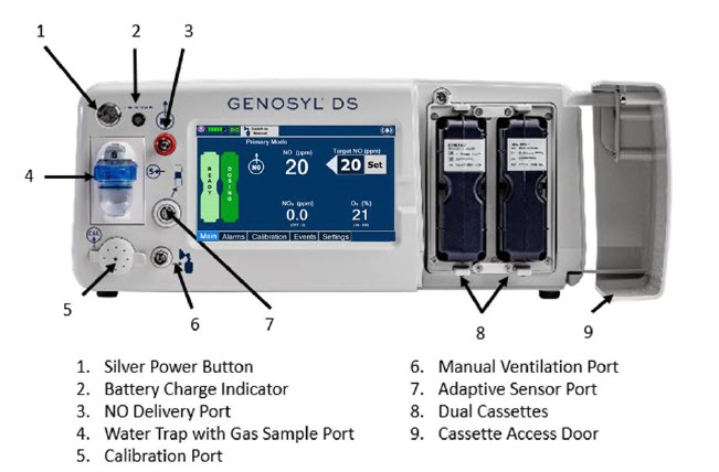
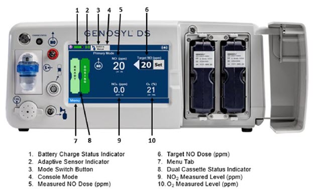
1. SYSTEM SET-UP AND CONNECTIONS
1.1. GENOSYL DS Set-Up and Mechanical Ventilator Circuit Schematic
NOTE: Naming conventions: The GENOSYL DS accessories and components consist of the GENOSYL DS Injection Assembly with Adaptive Sensor or GENOSYL DS Mixer Assembly with Adaptive Sensor, and the GENOSYL DS Gas Lines. Refer to Section 6.7 Table 4for when use of the Mixer Assembly with Adaptive Sensor is recommended. NOTE: All circuit components, including GENOSYL DS circuit components, should be changed out according to hospital protocol. WARNING: - ALWAYS use the GENOSYL DS in accordance with the indications, usage, contraindications, warnings, and precautions described in the GENOSYL prescribing information and labeling. Refer to latest approved prescribing information and labeling prior to use.
- The approved patient population for the GENOSYL DS as specified in the drug labeling for GENOSYL (nitric oxide) for inhalation, is limited to neonates. The GENOSYL DS is not intended to be used in other patient populations.
- ONLY use the GENOSYL DS, its parts, and accessories as instructed. Using non-specified components may result in product malfunction, injury or death.
- ALWAYS follow pre-use setup instructions for the routing and connections of tubing to avoid patient strangulation.
- MAKE SURE the System has all tubing connected as described in the instructions. Not connecting all tubing may result in inaccurate dosage and harm to the patient.
- DO NOT use accessories or cables other than those specified or provided by the manufacturer of this equipment, as this may result in increased electromagnetic emissions or decreased electromagnetic immunity of this equipment and result in improper operation.
1.2. Connections to Various Breathing Systems
1.2.1 Conventional Ventilators
- Bio-Med Devices CrossVent 2+
- Bio-Med Device MVP-10
- Dräger V500
- Dräger VN500
- Dräger V600
- Dräger VN600
- Dräger V800
- Dräger VN800
- Hamilton C1/T1
- Hamilton C6
- Hamilton G5
- Hamilton MR1
- Puritan Bennett 980
- Vyaire AVEA
WARNING: - ONLY use the GENOSYL DS with Bio-Med Crossvent 2+ with Constant Flow ON. Not doing so may lead to elevated NO 2levels or dose variability.
- The GENOSYL DS injects and samples gas from the patient respiratory circuit which may affect the triggering sensitivity of the ventilator. ALWAYS ensure the trigger sensitivity of the ventilator is checked after connecting the GENOSYL DS to the breathing circuit or when the dose is changed and adjust trigger sensitivity as necessary. Failure to do so may lead to ventilator auto cycling or apnea alarm.
- ALWAYS ensure the patient disconnect and high–pressure alarms are used with the ventilator.
CAUTION: - When using spontaneous breathing modeson respiratory device, NO 2levels may exceed 3.0 ppm when dosing ≥ 57 ppm NO into 100% FiO 2and maximum bias flow resulting in nitric oxide delivery interruption. Once sample value of NO 2is below 3.0 ppm, the Console will auto resume delivery of NO at set dose. Refer to the Operator's Manual Section 12.1.5 Table 13 for additional information.
- When using non-spontaneous breathing modeson respiratory device, NO 2levels may exceed 3.0 ppm when dosing ≥ 63 ppm NO or greater into 100% FiO 2and maximum bias flow resulting in nitric oxide delivery interruption. Once sample value of NO 2is below 3.0 ppm, the Console will auto resume delivery of NO at set dose. Refer to the Operator's Manual Section 12.1.5 Table 13 for additional information.
Table 1: Conventional Ventilator Compatibility Test Ranges Setting Range Unit Inspiratory Flow Rate 2-120 LPM Respiratory Rate 6-60 BPM Peak Inspiratory Pressure 0-70 cmH 2O Positive End-Expiratory Pressure (PEEP) 0-20 cmH 2O For applicable use scenarios, and when use of a mixer is required, see Section 6.7, Table 4.
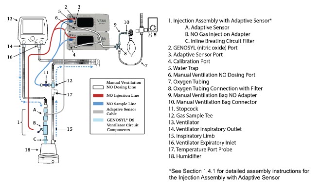
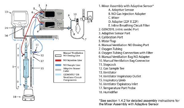
1.2.2 Non-Invasive Gas Delivery Systems
- Fisher and Paykel Optiflow Jr Breathing Circuit
- Fisher and Paykel Optiflow Breathing Circuit
Table 2: Non-Invasive Gas Delivery System Compatibility Test Ranges Setting Range Unit Fisher and Paykel Optiflow Jr 2 Flow Rate 0.5 - 25 LPM Fisher and Paykel Optiflow Flow Rate 5-60 LPM For applicable use scenarios, see Section 6.7, Table 4.
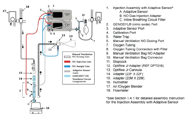
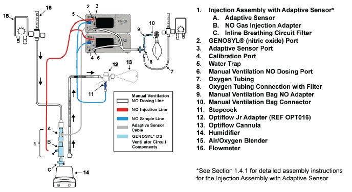
1.3 GENOSYL DS Ventilator Circuit Assembly Pre-Check
Follow the steps listed below for the initial System pre-check prior to completing the ventilator circuit assembly.
- Removeall items of the GENOSYL DS Parts / Components from packaging.
- Checkthe expiration date for each Cassette and Inline Breathing Circuit Filter to ensure use is within the expiration date.
WARNING:DO NOT use a Cassette that is beyond its expiration date. Using an expired Cassette may affect the Cassette's ability to provide the correct NO dosage to the patient, which may cause injury or death. - Visually inspectthe Water Traps on both Consoles to ensure they are installed and empty (Note: To empty the Water Trap, see Section 6.3.1).
WARNING: - ALWAYS empty Water Trap before each use, when prompted by the System, and when the trap is more than half full. Allowing the Water Trap to completely fill will occlude the Sample Line which will interrupt patient gas NO, NO 2, and O 2concentration monitoring. Failure to monitor the patient gas NO, NO 2, and O 2concentrations may result in patient injury.
- ALWAYS conduct Water Trap /Sample Line Leak Test every time you empty and replace the Water Trap, as failure to do so may lead to an incorrect NO reading, which can result in injury or death.
1.4 Assembling GENOSYL DS Injection Assembly with Adaptive Sensor
The Injection Assembly with Adaptive Sensor or the Mixer Assembly with Adaptive Sensor is the point of nitric oxide injection into the patient respiratory circuit. Only one type of assembly is required for each patient circuit. For certain scenarios, the Mixer Assembly with Adaptive Sensor is recommended to mix the NO gas with the gas supplied by the ventilator through a filter containing silica gel to provide intra-breath NO delivery. Refer to Table 4 for scenarios when a Mixer is recommended for use.
NOTE: When using a Mixer, an Inline Breathing Circuit Filter must be used. If a Mixer is not used, an Inline Breathing Circuit Filter as presented in Figure 8may be used, or an Injection Line Filter connected to the port on the Gas Injection Adapter may be used. 1.4.1 GENOSYL DS Injection Assembly with Adaptive Sensor
- Connectthe Inline Breathing Circuit Filter to the Gas Injection Adapter (22mm ID × 22 mm OD).
-
ConnectAdaptive Sensor to the inlet end of Gas Injection Adapter (22mm ID × 22 mm OD).
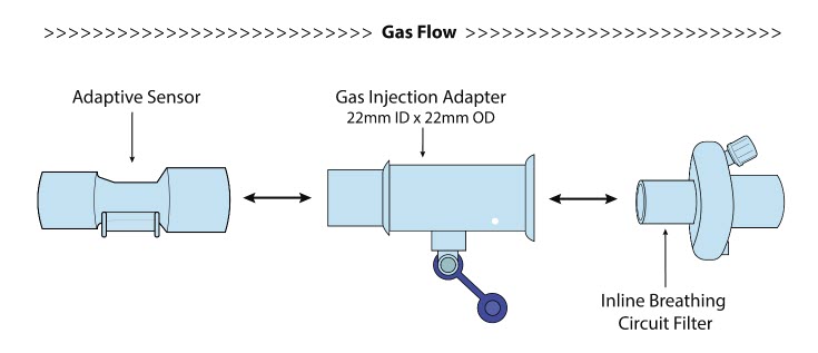
1.4.2 GENOSYL DS Mixer Assembly with Adaptive Sensor
- Connectthe Inline Breathing Circuit Filter to the Adapter (22mm ID × 22 mm OD).
- Connectthe Adapter (22mm ID × 22 mm ID) to the distal end of the Mixer.
- Connectthe Gas Injection Adapter to the proximal end of the Mixer.
- ConnectAdaptive Sensor to the proximal end of the Gas Injection Adapter.
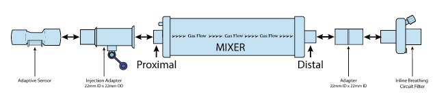
NOTE: To determine if the Injection Assembly with Adaptive Sensor or the Mixer Assembly with Adaptive Sensor is recommended, see Section 6.7, Table 4. 1.5 GENOSYL DS Console Connections
1.5.1 GENOSYL DS Gas Lines Connections
Follow the steps listed below to connect the Gas Lines to both Consoles.
-
Pushand
twistclockwise the short Y-end of the NO Injection Line (red) to the
"NO" port (red)on the front panel of the dosing Console.
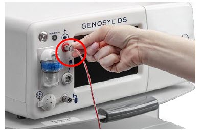
-
Pushand
twistthe short Y-end of the Sample Line (blue) to the
Gas Sample Port (blue)on the front of the Water Trap, attached to the dosing Console.
NOTE:Ensure the Sample Lines are connected to the Water Traps on both Consoles.
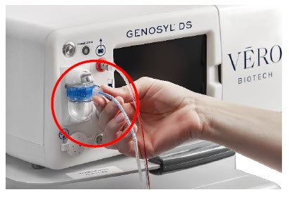
-
Pushand
twistthe short Y-end of the Manual Ventilation Line (clear) to the Manual Bagging Port on the front of the dosing Console.
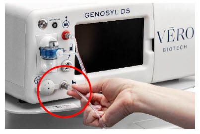
- Repeatsteps 1, 2, and 3 on the Back-up Console.
- ConnectAdaptive Sensor Cable to Adaptive Sensor Port on front of the dosing Console.
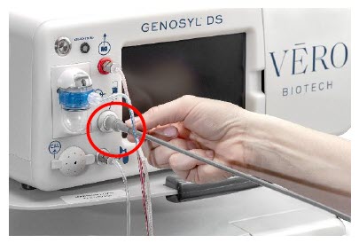
1.5.2 GENOSYL DS Sample Line Extension Connection
For use in the MR Environment when a longer sample line may be required, follow the steps listed below to connect a Sample Line Extension. It is recommended to install the extension prior to initiation of dose.
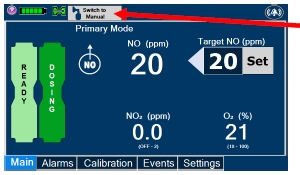
- If actively dosing, switchto Manual Dosing Mode prior to completing the following steps.
WARNING:Failure to switch to Manual Dosing Mode prior to installing a Sample Line Extension when the System is actively dosing may result in a spike in the NO dose delivered to the patient. 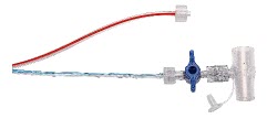
- Turnthe blue Stopcock Valve, attached at the Gas Sample Tee, to the closed position as shown.

- Pushand twistcounterclockwise the Luer-Lock Collar of the Sample Line to remove from the blue Stopcock Valve at the Gas Sample Tee.
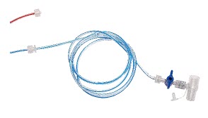
- Pushand twistclockwise the Luer-Lock Collar of the Sample Line onto the Sample Line Extension female connection.
- Pushand twistclockwise the Luer-Lock Collar of the Sample Line onto the blue Stopcock Valve at the Gas Sample Tee.
- PerformWater Trap/Sample Line Leak test, as instructed.
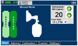
- If actively dosing, switchback to Primary Dosing Mode
1.5.3 GENOSYL DS Respiratory Circuit Connections
Follow the steps listed below to connect the Gas Lines to the Injection Assembly, Sample Tee, and Adaptive Sensor. If a Sample Tee already exists within the ventilator circuit, the Sample Line may be connected directly to the existing Sample Tee.
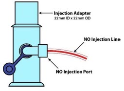
- Pushand twistclockwise the Luer-Lock Collar from the NO Injection Line onto the NO Injection Assembly.
NOTE:After connecting, the valve assembly may have rotated such that the orientation may appear different from what is shown here and on the display screen. 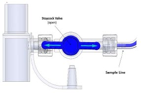
- Pushand twistclockwise the Luer-Lock Collar of the Sample Line onto the Sampling Port of the Gas Sample Tee.
NOTE: Skip this step if a Gas Sample Tee is already connected and in-line with the ventilator circuit. - Ensurethe blue Stopcock Valve is in the open position as shown.
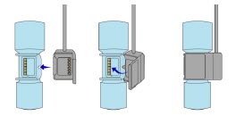
- Connectthe distal end of the Adaptive Sensor Cable to the Adaptive Sensor on the Injection Assembly
1.6 Manual Ventilation (Bag) Connection
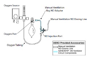
- Attachthe barbed end of the Manual Ventilation Bag NO Adapter into the oxygen tubing from the oxygen source.
- Attachthe other end of the NO Adapter to the oxygen port on the side of the Manual Ventilation Bag.
- Connectthe Manual Ventilation Line (clear) to the NO Injection Port of the Manual Ventilation Bag NO Adapter.
- Placethe Manual Ventilation Assembly in a clean accessible place if needed for future use.
1.7 Mechanical Ventilator Circuit Connections
Follow the steps outlined in this section to connect the GENOSYL DS Ventilator Circuit Assembly to the Mechanical Ventilator Circuit.
WARNING: - The GENOSYL DS injects and samples gas from the patient respiratory circuit which may affect the triggering sensitivity of the ventilator. ALWAYS ensure the trigger sensitivity of the ventilator is checked after connecting the GENOSYL DS to the breathing circuit or when the dose is changed and adjust trigger sensitivity as necessary. Failure to do so may lead to ventilator auto cycling or apnea alarm.
- ALWAYS ensure the patient disconnect and high–pressure alarms are used with the ventilator.
NOTE: All ventilator connections should be assembled and inspected prior to connecting to the mechanical ventilator circuit. - Disconnectthe Inspiratory Tubing from the humidifier and attach it to the proximal end of the Injection Assembly to the Adaptive Sensor.
- Attachthe distal end of the Injection Assembly to the humidifier.
- Insertthe Sample Tee into the ventilator circuit at the proximal end of the temperature probe closest to the patient.
2. SYSTEM START UP
2.1 Console Start-Up
CAUTION: - ONLY use the GENOSYL DS with the power cord supplied by the manufacturer. Use of a generic power cord may cause output voltage instability leading to a touch screen failure.
- ALWAYS ensure the power cord is firmly seated into the power supply and the wall outlet. A loose connection can result in damage to the device or faulty operation.
- Pushthe Circular Power Connectors into the back of the top and bottom Consoles.
- Connectthe main power cord to a grounded 120 V electrical outlet.
- Pressthe Black Rocker Power Switch, located on the back of each Console, to the right (ON position) to power on both Consoles.
- Pressthe Silver Power Button, located at the top left corner on the front panel of eachConsole, to turn on the display screens on both Consoles. The display screen will illuminate, and the Consoles will beep, indicating the power is on.
CAUTION:The System will conduct an internal self-test. If an alarm or failure message should occur, refer to Section 10 in the Operator's Manual to resolve the issue. NOTE: If the display screen does not turn on, see Troubleshooting, Section 10of the Operator's Manual. 2.2 Cassette Insertion & Water Trap / Sample Line Leak Test
The following steps should be taken on both the top and bottom Consoles. Upon the insertion of the Cassette, a test will be initiated on each Console to check and ensure the integrity of the Water Traps and Sample Line.
The Water Trap / Sample Line Leak Test is automatically initiated when a Cassette has been inserted,and the measured NO is less than 1.0 ppm.
WARNING:ALWAYS follow Cassette insertion instructions prior to Cassette insertion. Not inspecting the Cassette prior to insertion may lead to using a faulty Cassette, resulting in injury. - Confirmthe Cassette State Window on each Cassette is blue.
WARNING:DO NOT use the Cassette if the Cassette State Window is not blue. A Cassette State Window that is any color other than blue may affect the Cassette's ability to provide the correct NO dosage to the patient, which may cause injury or death. NOTE: If the Cassette State Window is not blue, see Troubleshooting, Section 10.8of the Operator's Manual. - Openthe Cassette Access Doors and inserttwo Cassettes into the Dosing Console and at least one Cassette into the Back-Up Console. Push until it clicks.
NOTE: The Water Trap / Sample Line Leak Test is automatically initiated when a Cassette has been inserted,and the measured NO is less than 1.0 ppm
After the first Cassette is fully inserted, the Operator will have 60 seconds to close the blue Stopcock Valveto perform the test.- Followthe onscreen instructions on both Consoles.
NOTE: - The screen will indicate the Water Trap / Sample Line Leak Test has started and the progress bar will be red until the stopcock valve has been closed, upon which it will then turn green if there is no leak detected.
- See Section 3.5for detail around dosing in Manual Dosing Mode.
- Followthe onscreen instructions on both Consoles.
CAUTION: Open the blue Stopcock Valve priorto pressing "Accept". Failure to do so will result in a line occlusion error. NOTE:If the Water Trap / Sample Line Leak Test fails, follow the onscreen instructions to resolve the issue. Also see Troubleshooting, Section 10.8of the Operator's Manual. 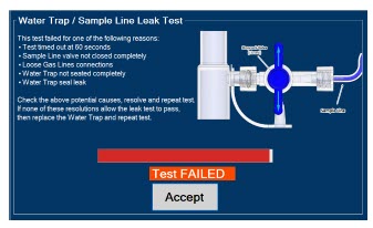
- If this screen is displayed, followthe onscreen instructions on both Consoles .
- PressYes on both Consoles to begin a new Water Trap / Sample Line Leak Test.
3 NITRIC OXIDE ADMINISTRATION
3.1 Nitric Oxide Dose Set-Up and Administration
WARNING: - MAKE SURE the System stabilizes to the prescribed concentration (ppm) of NO prior to leaving the Console unattended. Failure to do so could result in under delivery of the target NO, leading to injury or harm.
- ALWAYS constantly monitor the patient. System malfunctions can occur if device and patient are not monitored and can result in injury or death. Careful monitoring is required by care personnel whenever the System is used on a patient. The use of an alarm and a monitoring system does not give an absolute assurance of warning for every malfunction that may occur. Certain alarms may require immediate response.
- If the gas flow of the patient's respiratory device/ventilator should be interrupted or discontinued, the NO dose should be maintained by switching to Manual Dosing Mode or the target NO dose should be set to zero.
3.1.1 Setting a dose when using a circuit with an Adaptive Sensor
- Pressthe gray "Set" button on the display screen.
- Enterthe prescribed dose in ppm on the electronic keypad.
- PressOK to confirm the entry.
3.1.2 Setting the dose when using a circuit without an Adaptive Sensor
- Pressthe gray "Set" button on the display screen.
- ConfirmTotal Flow Range is appropriately selected.
- Enterthe prescribed dose in ppm on the electronic keypad.
- PressOK to confirm the entry.
NOTE: - The time to reach target dose may vary up to 10 minutes.
- If unable to set the dose in Primary Dosing Mode, see Troubleshooting, Section 10.8of the Operator's Manual.
3.2 Replacement of a Depleted Cassette
The GENOSYL DS automatically switches from the dosing Cassette to the secondary Cassette in the Dosing Console once the Cassette is depleted, when a secondary Cassette is properly inserted and preheated. After transition, the depleted Cassette is automatically ejected.
CAUTION:User should always have a secondary Cassette inserted in Dosing Console and preheated in order for auto transition to occur. User should replace depleted Cassette as soon as possible after ejection. ILLUSTRATION ACTION Warnings, Cautions and Notes 
NOTE The Console will automatically transition to the secondary Cassette if properly inserted and preheated. The screen to the left will be displayed during the transition process. 3.3 Manual Dosing Mode
NOTE: When entering Manual Dosing Mode, the set target dose in Primary Dosing Mode will carry over to Manual Mode if 5 ppm or greater. Less than 5 ppm set target dose in Primary Dosing Mode will default to 5 ppm dose in Manual Dosing Mode. However, dose and flow rate be adjusted for specific situations. The GENOSYL DS Smart Feedback System™ is disabled while in Manual Dosing Mode. To reinitiate the feedback loop, switch back to Primary Dosing Mode as soon as the situation permits 3.3.1 Manual Ventilation Use (Bagging)
WARNING: - ALWAYS ensure that the manual flow displayed on the Console matches the flow set into the resuscitation bag. Incorrect flow settings may result in an incorrect estimation of NO delivery. If the flow into the manual equipment is too low, there is risk of overdosing the patient with NO.
- ALWAYS squeeze the bag several times, after starting fresh gas flow, to empty residual gas in the bag prior to using the System to ventilate a patient. Failure to do so could result in higher NO2 levels being delivered to the patient.
- ALWAYS use the smallest bag adequate to deliver the desired tidal volume. Failure to do so could result in higher NO2 levels being delivered to the patient.
- ONLY use a manual resuscitation bag with the GENOSYL DS for a short time (e.g., less than one hour) when on battery only. Otherwise, the System may shut off and may result in injury or death.
- If the dilution flow rate displayed on the screen does not match the wall source, then the estimated NO may be inaccurate.
- Ensurethe oxygen source is set appropriately or adjust as needed.
- Pressthe button "Switch to Manual" on the Dosing Console.
- Press"Confirm" to switch to Manual Dosing Mode
- To resumeprimary dosing, see Section 3.4.
NOTE: - When switching to Manual Dosing Mode, dosing has been initiated at the same dose (ppm) as set in Primary Dosing Mode. If the dosing was set at "0" prior to pressing the "Switch to Manual" button, the estimated NO will also be at "0" and will need to be adjusted. If the primary dosing was set between 1 and 5 ppm prior to pressing the "Switch to Manual" button, the estimated NO dose will also be 5 ppm and may be adjusted.
- If an adjustment of the NO concentration is required, press the green up and down arrows.
- If an adjustment to the Dilution Flow Rate is required, press the LPM value and a drop-down menu will expand. Press the prescribed value. The new value will be highlighted in blue and the drop-down menu will collapse.
- In the event dose is initiated in Manual Dosing Mode, the Console will default to 20 ppm, which can be adjusted as needed.
- Pressthe "Switch to Primary" button at the top of the Manual Dosing Mode screen.
- Press"Confirm" to start dosing or "Cancel" to cancel.
NOTE:The NO dose used in Manual Dosing Mode will become the set target dose in Primary Dosing Mode. To adjust the dose of nitric oxide administered per hospital protocol/physician order. Follow the instructions listed below.
3.5.1 Adjusting the Dose when using a Circuit with an Adaptive Sensor
- Pressthe gray "Set" button to access the electronic keypad on the display screen on the Dosing Console.
- Enterthe prescribed (ppm) dose using the electronic keypad.
- Press"OK" to confirm the dose and to start dosing administration.
3.5.2 Adjusting the Dose and Flow Range when using a Circuit without an Adaptive Sensor
- Pressthe gray "Set" button to access the electronic keypad on the display screen on the Dosing Console.
- Enterthe prescribed (ppm) dose using the electronic keypad.
- AdjustTotal Flow Range, if necessary.
- Press"OK" to confirm the dose and to start dosing administration.
3.6 Console Use as a Back-Up
This section describes the process of activating the Cassette in the Back-Up Console. Delivery of NO will begin immediately upon Cassette activation.
- Pressthe "Set" button on the Back-Up Console which will display the NO dose electronic keyboard and Flow Section menu.
- ConfirmDose and Total Flow range is appropriately selected.
- Press"OK" to confirm entry
- ConnectAdaptive Sensor to the front of the new Dosing Console
NOTE: - The default Total Flow range displayed will be <2.5 LPM unless otherwise selected by the user.
- The Back-Up Console is now the and Flow Range Console.
- Dosing has been initiated at the default setting of 20 ppm.
4 CONSOLE SHUTDOWN AND CASSETTE DISPOSAL
WARNING:NEVER turn the rear power switch OFF until the System has gone through a controlled shutdown or instructed by VERO Technical Support. Turning the rear power switch OFF prematurely (e.g., while it is still in use) will immediately shut down the device. This may result in interruption in NO delivery to the patient, which may cause injury or death. CAUTION: - NEVER turn the rear power switch OFF until the System has gone through a controlled shutdown or instructed by VERO Technical Support. Turning the rear power switch OFF prematurely (e.g., while it is still in use) will immediately shut down the device and may cause improper operation upon restart.
4.1 Console Shutdown
If the administration of NO must be stopped, then the dose level must be set to "0" and the Cassette must be removed prior to shutting down the Console.
- Pressthe gray "Set" button to access the electronic keypad on the display screen.
- Setthe dose to "0" using the electronic keypad.
- Press"OK" to confirm the entry.
- If the "Settings" tab is not displayed, pressthe "Menu" tab to access the sub-level tabs.
- Pressthe "Settings" tab on the display menu.
- Pressthe red "System Shut Down" icon.
-
Reviewon screen prompt
.
NOTE:The screen will inform user if Cassette should be saved or disposed of. - Press"Confirm" to confirm shutdown.
-
Waituntil the Console shuts down, the display screen appears blank, and the Console emits an audible beep.
NOTE:The Console will inert any remaining contents from a dosing Cassette upon ejection rendering it unusable. If a Cassette has only been preheated, and not used for dosing, the contents have not been inerted and it can still be used. - Openthe Cassette Access Door.
- Removethe Cassette by pulling the Cassette straight out.
- Disposethe Cassette per hospital policy.
- Pressthe Black Rocker Power Switch to the "OFF" position.
- R epeat steps 1-12 for the other Console.
WARNING: NEVER turn the rear power switch OFF until the System has gone through a controlled shutdown or instructed by VERO Technical Support. Turning the rear power switch OFF prematurely (e.g., while it is still in use) will immediately shut down the device. This may result in interruption in NO delivery to the patient, which may cause injury or death. CAUTION:NEVER turn the rear power switch OFF until the System has gone through a controlled shutdown or instructed by VERO Technical Support. Turning the rear power switch OFF prematurely (e.g., while it is still in use) may cause improper operation. NOTE: If the System does not shut down, see Troubleshooting, Section 10.8of the Operator's Manual. 4.2 Cassette Disposal
Following dosing use, any remaining Cassette liquid contents are purged into an inerting chamber that is built into the Cassette, where the contents are chemically neutralized, rendering the Cassette safe for disposal. When the Cassette liquid contents are emptied into the inerting chamber, the Cassette State Window on the front of the Cassette reddens and bleaches from its original blue color, indicating the Cassette is depleted. The Cassette can now be disposed of per hospital policy.
5 ALARMS, ALERTS, AND TROUBLESHOOTING
WARNING:ALWAYS ensure patient safety before troubleshooting (such as an activated alarm) or replacing a problematic item. Not monitoring the patient prior to attending to an alarm can result in injury or death. 5.1 Alarms, Alerts, and Troubleshooting
Section 10 of the Operator's Manualcontains the system alarms and message in order of High (red), Medium (yellow), and Low Priority (turquoise) followed by Informational Messages (green). The table shows the alarm/symptom, the possible cause(s) of the alarm and recommended action to resolve the alarm. Additionally, on-screen troubleshooting support is available by either tapping an active alarm banner or by selecting the "Alarm Info" button on the "Alarms" tab. If the alarm/issue cannot be resolved, contact Technical Support at 877-337-4118.
A sample screen with an active alarm is shown below:
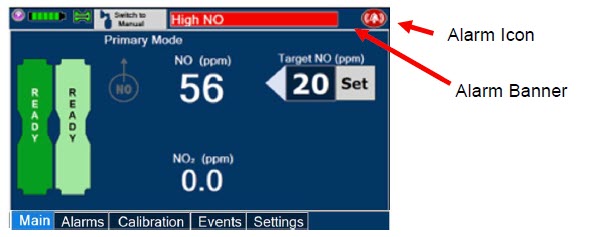
The alarm banner contains a drop-down menu containing a list of all alarms should there be multiple activated. The alarm icon is always present on the top right of the screen and tapping the icon will pre-silence or silence alarms. Refer to the table below for descriptions of each alarm status:
ALARM ICON DISPLAY DESCRIPTION 
No active alarm condition is detected on the Console. Tap this icon to activate the pre-silence feature. 
Alarms are actively pre-silenced. Countdown of time remaining appears under the icon. Pre-silence lasts for 120 seconds. Low/High NO, High NO 2, Low/High O 2, Water Trap Removed and Dosing Cassette Removed alarms are pre-silenced. Alarms will still be visible on alarm banner but audible alarm will not sound. 
Console has an active alarm condition that requires attention. Tap the icon to silence the alarm for 120 seconds. 
Console has an active alarm condition that requires attention and the alarms have been silenced. Countdown of time remaining appears under the icon. 6 MAINTENANCE
6.1 Calibration
WARNING: - ONLY use the calibration gas pressure regulators supplied by the manufacturer. Pressure regulators not supplied by the manufacturer may damage the sensors and may lead to patient injury.
- ALWAYS verify the correct NIST traceable calibration gas is being used and confirm the expiration date of the calibration gas prior to performing calibration. The use of incorrect or expired gas may result in inaccurate sensor readings and can lead to patient injury.
- NEVER perform NO or NO2 calibration within the MR scanner room. Calibration equipment is a potential projectile hazard.
CAUTION: - ALWAYS perform a full-scale calibration of the GENOSYL DS when prompted by the System prior to use.
- ALWAYS confirm the correct flow direction of the installed one-way check valve in the sampling tee to avoid over pressurization of the sampling system and damage to the device.
6.1.1 Air Calibration
Air Calibration will take up to 2 minutes. A progress bar is displayed in the lower lefthand corner of the display screen during the calibration process.
- Checkto make sure nothing is connected to the CAL port during Air Calibration.
- If the "Calibration" tab is not displayed, pressthe "Menu" tab to access the sub-level tabs.
- Pressthe "Calibration" tab on the display menu.
- Pressthe Low Range "Air" button.
- Pressthe blue "Start Calibration" button.
- Press"Accept " to continue once calibration is complete.
NOTE: If calibration fails, ensure that nothing is connected to or blocking the CAL port. 6.1.2 NO Calibration
WARNING: - DO NOT open the valve prior to connecting to the CAL port. Opening the valve first will expose the user to NO gas.
- DO NOT interrupt calibration until finished. If interrupted, calibration will be cancelled.
- DO NOT disconnect tubing from the calibration port prior to closing the valve. Disconnecting the tubing first will expose the user to NO gas.
NOTE: NO calibration takes approximately 2 minutes if not dosing, or five minutes if actively dosing. A progress bar is displayed in the lower left-hand corner of the display screen during the calibration process. - If the Calibration Tab is not displayed, pressthe "Menu" tab to access the sub-level tabs.
- Pressthe "Calibration" tab on the display menu.
- Pressthe High Range "NO" button.
- Pressthe blue "Start Calibration" button.
- Followthe onscreen instructions.
- Press"Accept " to continue once calibration is complete.
6.1.3 NO 2Calibration
WARNING: - DO NOT open the valve prior to connecting to the CAL port. Opening the valve first will expose the user to NO 2gas.
- DO NOT interrupt calibration until finished. If interrupted, calibration will be cancelled.
- DO NOT disconnect tubing from the calibration port prior to closing the valve. Disconnecting the tubing first will expose the user to NO 2gas.
NOTE:NO 2calibration takes approximately 2.5 minutes. A progress bar is displayed in the lower left-hand corner of the display screen during the calibration process. - If the Calibration Tab is not displayed, pressthe "Menu" tab to access the sub-level tabs.
- Pressthe "Calibration" tab on the display menu.
- Pressthe High Range "NO 2" button.
- Pressthe blue "Start Calibration" button
- Followthe onscreen instructions.
- Press"Accept " once calibration is complete.
6.2 Maintenance Schedule
The Console components require the following maintenance:
COMPONENT SCHEDULE Water Trap Per patient or as required (per Sample Line / Leak Test) Console 24 months or 10,000 pump hours, which ever is first The Console requires factory service every 24 months or 10,000 pump hours, whichever is first. The System will display an Information Message to remind the operator when service is required. Call Technical Support at 877-337-4118to schedule service.
6.3 Water Trap Maintenance
WARNING:ALWAYS empty Water Trap before each use, when prompted by the System, and when the trap is more than half full. Allowing the Water Trap to completely fill will occlude the Sample Line which will interrupt patient gas NO, NO 2, and O 2concentration monitoring. Failure to monitor the patient gas NO, NO 2, and O 2concentrations may result in patient injury. - RemoveWater Trap from Console by lifting latch and pulling the base of the Water Trap away from the Console.
- Removethe lid by pulling the lid from the base.
- Emptythe liquid contents.
- Cleanthe Water Trap per hospital policy and cleaning instructions in the Operator's Manual.
- Reattachthe lid by pushing it back onto base.
- Slidethe Water Trap back on the Console until it clicks into place.
6.3.2 Water Trap Replacement
WARNING: - ALWAYS use a Water Trap supplied by the manufacturer. Using an incorrect water trap could result in non-functioning or inaccurate sensor readings.
- ALWAYS conduct a Water Trap test every time you empty and replace the Water Trap, as failure to do so may lead to an incorrect NO reading, which can result in injury or death.
If the Water Trap / Sample Line Leak Test does not meet requirements and the Sample Line integrity is confirmed or remains occluded, replace the Water Trap.
- Removeold Water Trap from Console by lifting the latch and pulling the base of the Water Trap away from the Console.
- Slidenew Water Trap back on the Console until it clicks into place.
- Discardthe old Water Trap.
6.4 Battery
The battery will be serviced during scheduled maintenance performed by the manufacturer. If the need arises to replace the battery sooner than scheduled contact Technical Support at 877-337-4118to schedule a maintenance appointment.
During storage, the GENOSYL DS may be stored with the power off, but the external power supply should be connected at least once every 3 months to ensure a minimum charge is maintained on the internal battery.
WARNING:ONLY properly trained personnel should replace the battery. Incorrectly replacing the battery may result in a hazard such as excessive temperatures, fire, or explosion. 6.5 Cleaning
CAUTION: - ALWAYS power down the GENOSYL DS Console and disconnect the power to the Console when not in use. Failure to do so may lead to permanent damage to the Console.
- DO NOT sterilize (e.g., autoclave, gas sterilize) any of the components of the System, as this may compromise performance.
- DO NOT use harsh cleaning agents on the GENOSYL DS. Doing so may impair the structural integrity and/or function of the device.
- ONLY use a damp cloth to clean the Console and limit use of liquids around Console. Excess water can permanently damage the device.
- ALWAYS ensure the System is completely dry after cleaning before powering it ON. Failure to do so could result in equipment damage.
6.5.1 Enclosure, Connections, and Surfaces Other Than the Display
Prior to performing any cleaning or maintenance operations ensure that the GENOSYL DS Console has been completely powered down and that the AC/DC power supply external to the GENOSYL DS Console has been unplugged. Apply any mild detergent to cloth prior to wiping down the System. Gently clean the outer surface of the Console, Cart, and Adaptive Sensor Cable with a soft damp cloth and mild detergent or isopropyl alcohol (70%).
WARNING: - NEVER submerge the GENOSYL DS, Cassette, or non-disposable Adaptive Sensor Cable. Submerging in liquid will damage the System and could cause electrical shorts which may result in injury or death.
- DO NOT clean the GENOSYL DS with the power connected and the System turned ON, as this may lead to injury (e.g., shock). Unplug AC/DC power supply external to the System prior to cleaning.
6.5.2 Display Screen
Turn off Console and disconnect from AC power. Gently clean with a damp cloth.
CAUTION: - DO NOT touch or rub the display screen with abrasive cleaning compounds or organic solvents, as they may scratch and damage the screen.
- DO NOT spray or pour liquids directly on the controller or the display, as they may damage the screen.
6.6 Storage
6.6.1 Cart / Console Storage
The acceptable storage conditions for the cart/Console are shown in the following table.
Cart / Console Storage Temperature -20°C to 60°C Humidity 15% to 95%, non-condensing Pressure 57kPa to 110kPa During storage, the GENOSYL DS may be stored with the power off, but with the external power supply connected in which case the internal battery will be kept fully charged.
During storage, the GENOSYL DS may be stored with the power off, but the external power supply should be connected at least once every 3 months to ensure a minimum charge is maintained on the internal battery.
WARNING: - MAKE SURE the GENOSYL DS is connected to AC wall power to charge the battery a minimum of once every 3 months to maintain a minimum battery charge. Failure to recharge the Console battery for extended timeframes may result in full discharge of the battery. If a Battery Error message occurs during startup of the System, contact Technical Support at 877-337-4118for assistance.
- ONLY properly trained personnel should replace the battery. Incorrectly replacing the battery may result in a hazard such as excessive temperatures, fire, or explosion.
- ONLY store the GENOSYL DS as outlined in the storage instructions. Not storing the device in alignment with its storage instructions can cause the device to be unsafe and lead to injury or death.
6.6.2 Cassette / Accessory Storage
The GENOSYL DS may not function correctly if the Cassette or any of the System Accessories have been exposed to high levels of heat or humidity. Cassettes are supplied in a plastic container and should remain unopened until use. Cassettes should be stored at 25°C (77°F) with excursions permitted between 15°C to 30°C (59°F to 86°F). (See USP Controlled Room Temperature)
6.7 Ventilator Compatibility
Vero Biotech performs validation testing which determines the compatibility of ventilator/gas delivery systems with the GENOSYL DS. During this compatibility testing, the GENOSYL DS is evaluated for the following parameters while connected to each ventilator/gas delivery system:
- NO Dose Accuracy:Continuous and accurate delivery of a targeted dose of nitric oxide within ± 20% of setpoint or within +/- 2 ppm, whichever is greater.
- Respiratory Device Gas Delivery and Alarms:The respiratory device breath delivery and alarms continue to function as intended by the manufacturer across the range of operating conditions.
- NO 2Performance: NO 2remains within acceptable limits less than 1.0 ppm with 60% FiO2 and ≤40 ppm NO.
- O 2Dilution: Post dilution O 2level delivery is maintained within acceptable limits and conforms with the information presented in the GENOSYL DS Operator's Manual, Section 12.1.1, "Oxygen Dilution".
- NO Concentration Transients:NO concentration transients are ≤150% of mean concentration and as low as 0.0 ppm as long as the transient duration does not exceed 10% of the volumetric duration of the breath.
The testing performed demonstrated conformance with all specified requirements.
WARNING: - ALWAYS use the GENOSYL DS in accordance with the indications, usage, contraindications, warnings, and precautions described in the GENOSYL prescribing information and labeling. Refer to latest approved prescribing information and labeling prior to use.
- The approved patient population for the GENOSYL DS as specified in the drug labeling for GENOSYL (nitric oxide) for inhalation, is limited to neonates. The GENOSYL DS is not intended to be used in other patient populations.
The following ventilators and non-invasive gas delivery systems have been validated for use with the GENOSYL DS. Validated ventilators were not tested with a nebulizer. See Section 1for assembly instructions for Injection Assembly with Adaptive Sensor and Mixer Assembly with Adaptive Sensor.
Table 3: Details of Validated Systems Manufacturer Model Hospital * External Transport † Anesthesia Gas Machine ‡ Modes - * Refer to the Operator's Manual for additional Warnings, Cautions, and general information about use of the GENOSYL DS in the Hospital. Refer to Rev I, Section 7 for additional Warnings, Cautions, and information about use of the GENOSYL DS in the MR Scanner Room.
- † Refer to the Operator's Manual Rev I, Section 8 for additional Warnings, Cautions, and general information about use of the GENOSYL DS in External Transport.
- ‡ Refer to the Operator's Manual Rev I, Section 9 for additional Warnings, Cautions, and general information about use of the GENOSYL DS with Anesthesia Gas Machines.
Bio-Med Devices Crossvent 2+ - Cycle
- CPAP
Bio-Med Devices MVP-10 - Cycle
- CPAP
Dräger Fabius GS, Fabius GS Premium, Fabius Tiro - VC
- PC
- PS
- SIMV/PS
- Manual/ Spontaneous
Dräger V500, VN 500, V600, VN 600, V800, VN800 - VC-AC
- VC-SIMV
- VC-CMV
- PC-AC
- PC-SIMV
- PC-CMV
- PC-BIPAP
- VC-MMV
- PC-APRV
- PC-PSV
- SPN-CPAP/PS
- SPN-CPAP/VS
- SPN-PPS
GE Aisys CS2 - VCV
- PCV
- PCV-VG
- PSVPro
- CPAP+PSV
- SIMV PCV
- SIMV VCV
- SIMV PCV-VG
- Manual
Hamilton C1/MR1 - PCV+
- PSIMV+
- APVcmv
- APVsimv/SIMV+
- ASV
- DuoPAP
- APRV
- SPONT
- NIV
- NIV ST
- nCPAPA
- nCPAP PC
Hamilton C6 - APVcmv
- APVsimv
- PCV+
- PSIMV+
- DuoPAP
- APRV
- SPONT
- ASV
- NIV
- NIV-ST
- nCPAP-PS
Hamilton G5 - (S)CMV
- P-CMV
- P-SIMV
- APVcmv
- APVsimv
- ASV
- DuoPAP
- APRV
- SPONT
- VS
- NIV
- NIV-ST
- nCPAP-PS
- SIMV
Hamilton T1 - PCV+
- PSIMV+
- APVcmv
- APVsimv/SIMV+
- ASV
- DuoPAP
- APRV
- SPONT
- NIV
- NIV ST
- nCPAP
- nCPAP PC
Puritan Bennett 980 - A/C PC
- A/C VC
- A/C VC+
- NIV AC PC
- NIV AC VC
- BiLevel
- BiLevel PC PS
- BiLevel PC TC
- NIV CPAP
- SPONT VS
- NIV SPONT PS
- SPONT TC
- SPONT PAV+
Vyaire Medical Inc. AVEA - Volume A/C
- Pressure A/C
- Volume SIMV
- Pressure SIMV
- CPAP/PSV
- PRVC A/C
- PRVC SIMV
- APRV/BiPhasic
- TCPL A/C
- TCPL SIMV
- Nasal CPAP/IMV
Fisher & Paykel Optiflow Jr 2 Breathing Circuit N/A Fisher and Paykel Optiflow Breathing Circuit N/A Table 4: Validated Compatibility with and without Inline Mixer
At the lowest tested rate of 6 BPM, a Mixer may be used to reduce intra-breath dose variability as outlined in Table 4 below. Intra-breath dose variability was not observed at a respiratory rate of 60 BPM.
See Section 1for assembly instructions for Injection Assembly with Adaptive Sensor and Mixer Assembly with Adaptive Sensor.
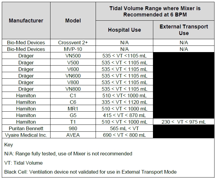
VERO Biotech and GENOSYL are registered trademarks of VERO Biotech Inc.
© 2025 VERO Biotech. Printed in U.S.A. LBL-602503 Rev H JUNE 2025
Please read full prescribing information enclosed.
877.337.4118 | vero-biotech.com -
INSTRUCTIONS FOR USE
USING THE GENOSYL ®DELIVERY SYSTEM WITH AN ANESTHESIA GAS MACHINE
STEP 1: POWER ON THE GENOSYL DELIVERY SYSTEM
Refer to Operator's Manual Section 4.1 for detailed instructions.- Push circular power connectors into the back of the top and bottom Consoles.
- Connect the main power cord to a grounded 120V electrical outlet.
- Press the black rocker power switch on the back of each Console to the right (ON Position).
- Press the silver power button, located in the top left corner of the front panel of each Console.
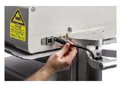
NOTE Refer to Operator's Manual for use of the GENOSYL DS in the MR environment 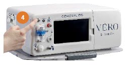
- * Specific use cases may require the use of an Inline Mixer which is used to mix the NO gas with the gas supplied by the AGM through a filter containing silica gel to provide intra-breath NO delivery for certain scenarios. Refer to Table 6 in the Operator's Manual for specific use cases and Section 3.4.2 for additional assembly instructions.
STEP 2: REMOVE ALL GENOSYL DS COMPONENTS FROM PACKAGING
Refer to Operator's Manual Section 3.3 for detailed instructions.
This includes a Gas Injection Adapter, two Inline Breathing Circuit filters, Adaptive Sensor, Adaptive Sensor Cable, Sample Tee (if not already present in dual limb circuit), Manual Bag Adapter, Gas Lines and two Cassettes. *
STEP 3: ATTACH GAS LINES TO CONSOLES
Refer to Operator's Manual Section 3.5 for detailed instructions.- Push and twist clockwise the short Y-end of the NO Injection Line (red) to the "NO" port (red) on the front panel of both Consoles.
- Push and twist clockwise the short Y-end of the Sample Line (blue) to the Gas Sample Port (blue) on the Water Trap attached to both Consoles.
- Push and twist clockwise the end of the clear Manual Ventilation Line (clear) to the Manual Ventilation Port (clear) on the front of both Consoles.
- Connect the Adaptive Sensor Cable to the Adaptive Sensor Port on the front of the Dosing Console.

STEP 4: ATTACH GAS LINES TO ANESTHESIA CIRCUIT INSPIRATORY LIMB
Refer to Operator's Manual Section 9.2 for detailed instructions.
An Inline Mixer may be required under some ventilation settings to assure NO dosing accuracy.
The settings where use of Inline Mixer is recommended are found in Section 9, Table 6 and instructions for the Inline Mixer Assembly with Adaptive Sensor are found in Section 3.4.2 of the Operator's Manual.- Check the expiration date for each Inline Breathing Circuit Filter to ensure use is within the expiration date.
- Connect the Inline Breathing Circuit Filter to the Gas Injection Adapter (22 mm ID × 22 mm OD).
- Connect the Adaptive Sensor to the inlet end of the Gas Injection Adapter (22mm ID × 22mm OD).
- Attach the Injection Assembly with Adaptive Sensor to the Gas Injection Adapter on the Inspiratory Port on the AGM.
- Attach the inspiratory limb of the breathing circuit to the Inline Breathing Circuit Filter. If the breathing circuit has a Sample Gas Tee inserted, ensure this limb of the circuit is attached to the Inline Breathing Circuit Filter.
- Insert the Gas Sample Tee into the inspiratory limb of the breathing circuit, 6-12" from the patient wye.
- Insert the Inline Breathing Circuit Filter between the Expiratory Port and expiratory limb. Skip this step if a bacterial filter is already present in the expiratory limb of the breathing circuit.
- Attach the expiratory limb of the breathing circuit to the Inline Breathing Circuit Filter on the Expiratory Port on the Anesthesia Machine.
- Push and twist clockwise the luer-lock collar from the NO injection line onto the NO injection port of the Gas Injection Adapter on the Injection Assembly.
- Push and twist clockwise the luer-lock collar of the Stopcock on the Sample Line onto the Sampling Port of the Gas Sample Tee.
- Connect the distal end of the Adaptive Sensor Cable to the Adaptive Sensor on the Injection Assembly.
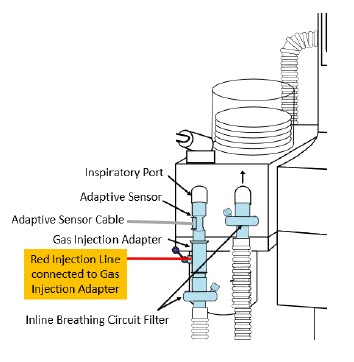
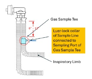
NOTE - Connections to various AGMS are unique to each manufacturer as well as their corresponding disposable circuits.
- A dual limb anesthesia breathing circuit should be used for iNO delivery with the GENOSYL DS.
- The GENOSYL DS Sample Line must be placed on the INSPIRATORY limb of the breathing circuit between 6 and 12 inches from the patient wye. If the sampling line is placed greater than 6 inches from the patient wye it minimizes the sampling of mixed inspired/expired gas concentrations and if placed less than 12 inches from the patient wye it ensures correct iNO and NO 2measurement.
To ensure assembly setup is correct, refer to Figure 1. Anesthesia Machine Setup on reverse side.
STEP 5: ASSEMBLE MANUAL VENTILATION WITH THE GENOSYL DS
Refer to Operator's Manual Section 3.6 for detailed instructions.- Attach the barbed end of the Manual Ventilation Bag NO Adapter into the oxygen tubing from the oxygen source.
- Attach the other end of the NO Adapter to the oxygen port on the side of the Manual Ventilation Bag.
- Connect the Manual Ventilation Line (clear) to the NO Injection Port of the Manual Ventilation Bag NO Adapter.
- Place the Manual Ventilation Assembly in a clean accessible place if needed for future use.
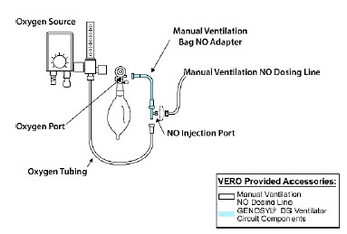
To ensure assembly setup is correct, refer to Figure 1. Anesthesia Machine Setup below.
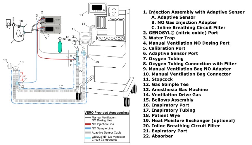
WARNING - ALWAYS use the GENOSYL DS in accordance with the indications, usage, contraindications, warnings, and precautions described in the GENOSYL prescribing information and labeling. Refer to latest approved prescribing information and labeling prior to use.
- ALWAYS use the Anesthesia Gas Machine (AGM) in accordance with the manufacturer's instructions.
- The approved patient population for the GENOSYL DS as specified in the drug labeling for GENOSYL (nitric oxide for inhalation (iNO)) is limited to neonates. The GENOSYL DS is not intended to be used in other patient populations.
- Ensure the Injection Assembly and the Gas Sample Tee are BOTH inserted on the inspiratory limb of the circuit.
- The flow out of the anesthesia gas machine via the INSPIRATORY breathing circuit limb must pass through the GENOSYL DS Gas Injection Assembly.
- The GENOSYL DS injects and samples gas from the patient respiratory circuit which may affect the triggering sensitivity of the anesthesia gas machine (AGM). ALWAYS ensure the trigger sensitivity of the AGM is checked after connecting the GENOSYL DS to the breathing circuit and starting iNO delivery or when the dose is changed, and adjust trigger sensitivity as necessary. Failure to do so may lead to AGM auto cycling or apnea alarm.
- ALWAYS ensure the patient disconnect and high-pressure alarms are used with the AGM.
CAUTION - Pneumatic Nebulizers will dilute the delivered nitric oxide dose.
- The Adaptive Sensor is recommended for use with anesthesia gas machines (AGMs). When using an AGM without the Adaptive Sensor, transient dose excursions outside of the set NO dose may occur during Cassette transition, and changes in breathing circuit flow may cause fluctuations in measured levels of NO and NO 2when using the manual ventilation bag integrated with the AGM.
- When using anesthesia gas machines, NO 2levels may exceed 3.0 ppm when dosing ≥ 58 ppm NO into 100% FiO 2, resulting in nitric oxide delivery interruption. Once sample value of NO 2is below 3.0 ppm, the Console will auto resume delivery of NO at set dose.
- Rebreathing validation testing was performed with semi-closed breathing systems. Non-rebreathing validation testing was performed with semi-open breathing systems. The GENOSYL DS has not been evaluated with fully open or fully closed anesthesia breathing systems.
NOTE - The GENOSYL DS performs as specified in this Operator's Manual independent of anesthetic agent, anesthetic agent concentration, and fresh gas flow rate.
- Changes in the AGM ventilator settings, fresh gas flow rate, or pushing the Oxygen Flush button by the user may cause brief transient changes in the measured NO value.
- Use of an Adaptive Sensor is recommended for use with AGMs. If not using an Adaptive Sensor:
- And using rebreathing fresh gas flow rates, it is recommended that the < 2.5 LPM Total Flow setting be selected.
- And using non-rebreathing fresh gas flow rates, it is recommended that the Total Flow selection based on the minute volume be selected.
- When using the manual ventilation bag integrated with the AGM, nitric oxide can be delivered by leaving the Console in Primary Dosing Mode. Nitric oxide will be delivered through the Injection Assembly into the anesthesia gas circuit.
- In the event of anesthesia gas machine failure, NO delivery can be continued using Manual Dosing Mode on the GENOSYL DS with a manual bag connected to the manual ventilation port on the front of the Console and an alternative gas source than the AGM.
INSERTING A CASSETTE
Refer to Operator's Manual Section 4.2 for detailed instructions.STEP 1: CHECK THE CASSETTE - Remove Cassettes from packaging.
- Check the expiration date for each Cassette to ensure use is within the expiration date.
- Confirm Cassette status indicator on each Cassette is blue.

STEP 2: INSERT CASSETTE INTO THE CONSOLE - Open the Cassette Access Door and insert two Cassettes into the Dosing Console and at least one Cassette into the Back-up Console. Push until it clicks.
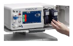
STEP 3: COMPLETE WATER TRAP / SAMPLE LINE LEAK TEST - Follow on-screen instructions on both Consoles to complete Water Trap / Sample Line Leak Test.
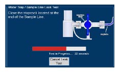
INITIATING A NITRIC OXIDE DOSE
Refer to Operator's Manual Section 5.1.1 for detailed instructions.STEP 1: INITIATE NITRIC OXIDE ADMINISTRATION - Press the gray Set button on the display screen.
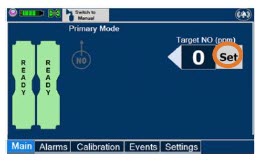
- Enter the prescribed dose in ppm on the electronic keypad.
- Press OK to confirm entry.
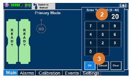
ADJUSTING THE NITRIC OXIDE DOSE
Refer to Operator's Manual Section 5.2.1 for detailed instructions.STEP 1: SET FLOW - Press the gray "Set" button to access the electronic keypad on the display screen on the Dosing Console.
- Enter the prescribed ppm dose using the electronic keypad.
- Press "OK" to confirm the dose and to start dosing administration.

MANUAL VENTILATION MODE USING EXTERNAL RESUSCITATION BAG
Refer to Operator's Manual Section 5.4.1 for detailed instructions.WARNING - ALWAYS ensure that the manual flow displayed on the Console matches the flow set into the resuscitation bag. Incorrect flow settings may result in an incorrect estimation of NO delivery. If the flow into the manual equipment is too low, there is risk of overdosing the patient with NO.
- ALWAYS squeeze the bag several times, after starting fresh gas flow, to empty residual gas in the bag prior to using the System to ventilate a patient. Failure to do so could result in higher NO 2levels being delivered to the patient.
- ALWAYS use the smallest bag adequate to deliver the desired tidal volume. Failure to do so could result in higher NO 2levels being delivered to the patient.
- ONLY use a manual resuscitation bag with the GENOSYL DS for a short time (e.g., less than one hour) when on battery only. Otherwise, the System may shut off and may result in injury or death.
STEP 1: SWITCHING TO MANUAL DOSING MODE - Ensure the oxygen flow source is set appropriately or adjust as needed.
- Press the button "Switch to Manual" on the Dosing Console.
- Press Confirm to switch to Manual Dosing Mode.
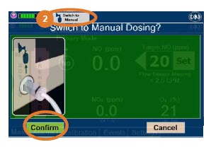
WARNING If the dilution flow rate displayed on the screen does not match the wall source, then the estimated NO may be inaccurate. STEP 2: SWITCHING BACK TO PRIMARY DOSING MODE - Press the "Switch to Primary" button at the top of the Manual Dosing Mode screen.
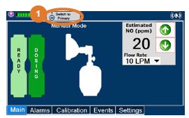
- Press "Confirm" to start dosing or "Cancel" to cancel.
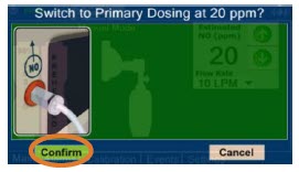
GAS SAMPLING DURING AEROSOL DELIVERY
Refer to Operator's Manual Section 3.8 for detailed instructions.- Place the medication nebulizer downstream of the Gas Sample Tee on the inspiratory limb.
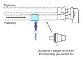
- Insert and connect the Sample Line Filter between the Sample Line and blue Stopcock. Refer to Operator's Manual Section 3.5.3 for detailed instructions to connect a Sample Line Filter.
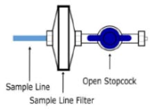
NOTE NOTE This placement avoids contamination of the sample system and prevents Line Occlusion Alarm from occurring. Replace filter after each treatment period. Change the filter if necessary due to Line Occlusion Alarm. CAUTION Pneumatic Nebulizers will dilute the delivered nitric oxide dose. CONSOLE USE AS A BACK-UP
Refer to Operator's Manual Section 5.5 for detailed instructions.- Press the "Set" button on the Back-up Console which will display the NO dose electronic keypad and Flow Selection menu.
- Confirm Dose and Total Flow range is appropriately selected.
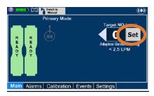
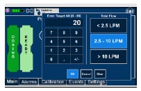
- Press "OK" to confirm entry
- Connect the Adaptive Sensor Cable to the front of the new Dosing Console.
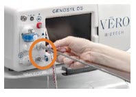
POWERING DOWN THE SYSTEM
Refer to Operator's Manual Section 6.1 for detailed instructions.STEP 1: POWERING DOWN THE SYSTEM - Press the gray "Set" button to access the electronic keypad on the display screen.
- Set the dose to "0" using the electronic keyboard.
- Press "OK" to confirm the entry.
- If the Settings Tab is not displayed, press the "Menu" tab to access the sub-level tabs.
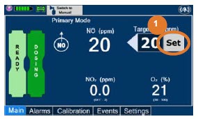
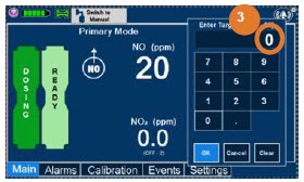
- Press the "Settings" tab on the display menu.
- Press the red "System Shutdown" icon.
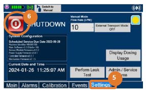
- Review on-screen prompt.
- Press "Confirm" to confirm shutdown.
- Wait until the Console shuts down, the display screen appears blank, and the Console emits an audible beep.
- Open the Cassette Access Door.
- Remove the Cassettes by pulling the Cassette straight out.
- Dispose of the inerted Cassette per hospital policy.

NOTE The Console will inert any remaining contents from a dosing Cassette upon ejection, rendering it unusable. If a Cassette has only been preheated, and not used for dosing, the contents have not been inerted and it can still be used. The Cassette State Window will remain blue on Cassettes that have not been inerted. 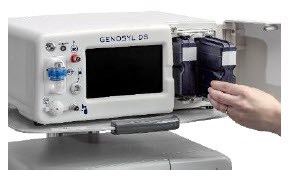
EMPTY AND REPLACE WATER TRAP
Refer to Operator's Manual Section 11.4 for detailed instructions.STEP 1: EMPTY THE WATER TRAP - Remove Water Traps from both Consoles by lifting latch and pulling the base of the Water Trap away from the Console.
- Remove the lids by pulling the lid away from the base.
- Empty the liquid contents.
- Reattach the lids by pushing back onto base.
- Slide the Water Traps back on both Consoles until they click into place.


CRITICAL ALARM TROUBLESHOOTING
Refer to Operator's Manual Section 10 for detailed instructions.ALARM CONDITION TROUBLE SHOOTING LINE OCCLUSION (Sample)
Message Box:
None
Banner:
In this fallback mode, the Console will continue delivering nitric oxide in an open loop mode at the last commanded dose until the line occlusion is resolved. - Ensure blue Sample Line Stopcock is in the open position.
- Remove Sample Line Filter, replace if needed.
- Empty Water Tap.
- If occlusion persists after emptying, replace Water Trap.
- Inspect entire length of blue sample line for kinks or occlusions.
- Replace gas lines if kink or occlusion cannot be resolved.
- If issue is still not resolved, switch over to Back-up Console.
- Contact Technical Support.
WATER TRAP NOT DETECTED
Message Box:
Banner: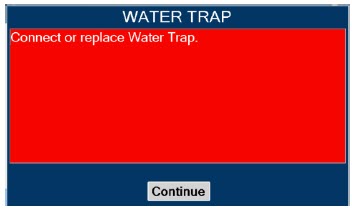

In this fallback mode, the console will continue delivering nitric oxide in an open loop mode at the last commanded dose until the water trap is replaced and the leak check is passed. - Re-seat Water Trap.
- Insert new Water Trap.
- Switch over to Back-up Console.
- Call Technical Support.
LOW NO ALARM
Message Box:
None
Banner:
- Verify GENOSYL DS gas line connections are tight by loosening then retightening each connection on the red injection and blue sample lines.
- Verify proper placement of Injection Assembly and Sample adapter within the respiratory circuit.
- Ensure gas sample tee is placed 6 to 12 inches from the patient wye adapter.
- Replace adapters that have evidence of excessive condensation.
- Check the respiratory circuit for the presence of leaks.
- If not using an Adaptive Sensor, confirm total flow range is properly selected.
- Allow time for the sensor measurement to adjust while completing the next steps.
- Push on Cassette to ensure it is fully seated.
- Empty Water Trap. Replace Water Trap if necessary.
- If Cassette is depleted, insert a second Cassette if not already present. If auto transition does not occur, switch to Back-up Console.
- Ensure dose and flow are set within specifications. (see Operator's Manual Section 12.1.4) Liters per minute multiplied by ppm should not exceed 800. (Example 40 LPM × 20ppm = 800)
- Go to alarms screen and check the NO alarm setting. Set the alarm to the desired setting.
- If sensor measurement does not adjust, switch over to Back-up Console.
- Contact Technical Support.
HIGH NO ALARM
Message Box:
None
Banner:
- Verify flow is present in the patient's respiratory circuit.
- Allow time for the sensor measurement to adjust while completing the next steps.
- Verify GENOSYL DS gas line connections are tight by loosening then retightening each connection on the red injection and blue sample lines.
- Verify proper placement of injection assembly and sample adapter within the respiratory circuit.
- Replace adapters that have evidence of excessive condensation.
- Go to the Alarms screen and check the NO alarm setting. Set alarm to the desired setting.
- If the sensor measurement does not adjust, switch to Back-up Console.
- Contact Technical Support.
HIGH NO 2ALARM
Message Box:
None
Banner:
- Verify flow is present in the patient's respiratory circuit.
- Consider increasing bias flow, if applicable
- Allow time for the sensor measurement to adjust while completing the next steps.
- Verify GENOSYL DS gas line connections are tight by loosening then retightening each connection on the red injection and blue sample lines.
- Verify proper placement of injection assembly and sample adapter within the respiratory circuit.
- Replace adapters that have evidence of excessive condensation.
- Go to the Alarms screen and check the NO 2alarm setting. Set alarm to the desired setting.
- If the sensor measurement does not adjust, switch to Back-up Console
- Contact Technical Support.
This section contains troubleshooting instructions for common high priority alarms and messages and common possible causes in the OR setting of use. For other high priority alarms and messages and possible causes please refer to the Operator's Manual Section 10.3.
For technical support, contact the Partnership365™ Care Team at 1.877.337.4118
VERO Biotech and GENOSYL are registered trademarks of VERO Biotech Inc.
© 2025 VERO Biotech Inc. All rights reserved. MMC-602936 Rev. B June 2025
Please refer to full Prescribing Information and Operators Manual
vero-biotech.com | 1.877.337.4118aarc
ZENITH AWARD
2024 - PRINCIPAL DISPLAY PANEL - 216 L Cartridge Label
-
INGREDIENTS AND APPEARANCE
GENOSYL
nitric oxide gasProduct Information Product Type HUMAN PRESCRIPTION DRUG Item Code (Source) NDC: 72385-002 Route of Administration RESPIRATORY (INHALATION) Active Ingredient/Active Moiety Ingredient Name Basis of Strength Strength NITRIC OXIDE (UNII: 31C4KY9ESH) (NITRIC OXIDE - UNII:31C4KY9ESH) NITRIC OXIDE 0.98 mg in 1 L Packaging # Item Code Package Description Marketing Start Date Marketing End Date 1 NDC: 72385-002-01 216 L in 1 CARTRIDGE; Type 0: Not a Combination Product 12/28/2022 Marketing Information Marketing Category Application Number or Monograph Citation Marketing Start Date Marketing End Date NDA NDA202860 12/28/2022 Labeler - VERO BIOTECH, INC. (872672477) Registrant - VERO BIOTECH, INC. (872672477) Establishment Name Address ID/FEI Business Operations VERO BIOTECH, INC. 872672477 manufacture(72385-002)

Trademark Results [GENOSYL]
Mark Image Registration | Serial | Company Trademark Application Date |
|---|---|
 GENOSYL 87772550 not registered Live/Pending |
VERO BIOTECH, LLC 2018-01-26 |
 GENOSYL 85981080 4496333 Live/Registered |
GeNO LLC 2011-12-02 |
 GENOSYL 85485604 4700107 Live/Registered |
VERO BIOTECH, LLC 2011-12-02 |
© 2026 FDA.report
This site is not affiliated with or endorsed by the FDA.